
Composite cable and composite harness

a composite cable and cable technology, applied in the direction of cables, insulated conductors, conductors, etc., can solve the problems of deteriorating working environment, and achieve the effect of preventing the deterioration of the working environmen

Active Publication Date: 2017-09-14
HITACHI METALS LTD
View PDF17 Cites 10 Cited by
  • Summary
  • Abstract
  • Description
  • Claims
  • Application Information

AI Technical Summary

Benefits of technology

This patent is for a way to make cables and harnesses that are more flexible and durable, while also improving the environment in which they are used.

Problems solved by technology

The composite cable disclosed by JP-A-2014-135153 has a problem that when terminating the cable, a lubricant such as talc powder may be scattered in a workplace so that the working environment deteriorates.

Method used


Image

  • Composite cable and composite harness
  • Composite cable and composite harness
  • Composite cable and composite harness

Examples


embodiment

[0029]An embodiment of the invention will be described below in conjunction with the appended drawings.

[0030]Description of Vehicle in Which Composite Cable is Used

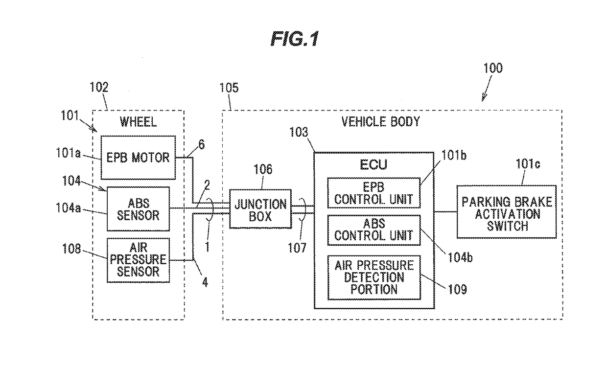
[0031]FIG. 1 is a block diagram illustrating a configuration of a vehicle in which a composite cable in the present embodiment is used.

[0032]As shown in FIG. 1, a vehicle 100 is provided with an electric parking brake (hereinafter, referred to as “EPB”) 101 as an electrically operated brake unit.

[0033]The EPB 101 is provided with an EPB motor 101a and an EPB control unit 101b.

[0034]The EPB motor 101a is a wheel-side device mounted on a wheel 102 of the vehicle 100. The EPB control unit 101b is mounted on an ECU (electronic control unit) 103 which is a vehicle body-side device of the vehicle 100. Alternatively, the control unit 101b may be mounted on a control unit other than the ECU 103, or may be mounted on a dedicated hardware unit.

[0035]The EPB motor 101a is provided with a piston to which brake pads are attached even...


PUM


Abstract

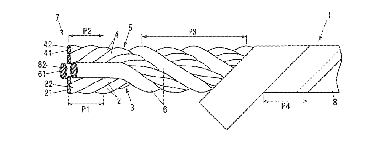
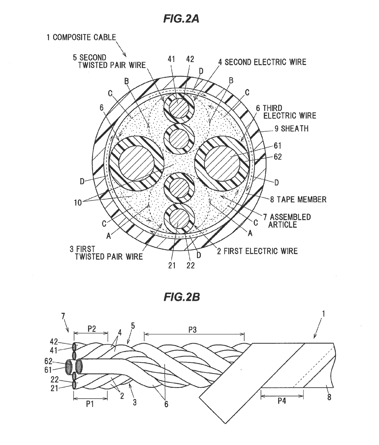
A composite cable includes a first twisted-pair wire formed by twisting a pair of first electric wires, a second twisted-pair wire formed by twisting a pair of second electric wires, a pair of third electric wires arranged between the first and second twisted-pair wires in a circumferential direction, each third electric wire having a larger outer diameter than the first and second electric wires, and a tape member spirally wound around an assembled article that is formed by twisting the first twisted-pair wire, the second twisted-pair wire and the pair of third electric wires together. The two twisted-pair wires have the same twist direction, the twist direction of the two twisted-pair wires is different from a twist direction of the assembled article, and the twist direction of the assembled article is different from a winding direction of the tape member.

Description

[0001]The present application is based on Japanese patent application No. 2016-045447 filed on Mar. 9, 2016, the entire contents of which are incorporated herein by reference.BACKGROUND OF THE INVENTION[0002]1. Field of the Invention[0003]The invention relates to a composite cable and a composite harness and, in particular, to a composite cable and a composite harness which are used in a vehicle such as automobile for connection between a wheel side and a vehicle body side.[0004]2. Description of the Related Art[0005]In recent years, electrically operated brake units are used in vehicles such as automobiles.[0006]Electro-mechanical brakes (EMB) and electric parking brakes (EPB) are known as such electrically operated brake units.[0007]The electro-mechanical brakes, also simply called electric friction brake or electric brake, are configured such that a rotational drive force of a dedicated electric motor mounted on each wheel of a vehicle is controlled according to the operation amo...

Claims


Application Information

Patent Timeline
IPC IPC(8): H01B11/04B60T13/74B60R16/02H01B3/00
CPCH01B11/04H01B3/002B60T2270/10B60R16/0215B60T13/741B60R16/0207B60T7/107B60T13/74H01B7/0045
Inventor HAYAKAWA, YOSHIKAZUMURAYAMA, TOMOYUKIESHIMA, HIROTAKAOKA, FUMIHITOFUTATSUMORI, TAKAHIRO
Owner HITACHI METALS LTD
Learn More