Method of inspecting a fuel cell system, and the fuel cell system

a fuel cell and system inspection technology, applied in the direction of transportation hydrogen technology, climate sustainability, electric power generation, etc., can solve the problems of difficult identification of whether the fuel economy change, increase the cost, and worsen the fuel economy, so as to facilitate the consumption of fuel gas supplied from the sub-tank, the structure is excellent, and the determination can be made accurately.

Active Publication Date: 2017-09-14
HONDA MOTOR CO LTD
View PDF5 Cites 2 Cited by
  • Summary
  • Abstract
  • Description
  • Claims
  • Application Information

AI Technical Summary

Benefits of technology

[0018]Alternatively, even in the case where the additional sensor is provided for the fuel cell system, it becomes possible to double-check occurrence of adhesion of the second switching valve, and achieve the excellent structure in terms of the fail safe operation.
[0019]The fuel cell system may discard the fuel gas and water remaining in the fuel cell during the double switching valve open state. Therefore, in the state where the remaining fuel gas and water are reduced, whether or not adhesion of the second switching valve has occurred is determined based on the change in the detection value of the pressure sensor in the second switching valve open state. Accordingly, in the second solenoid valve open state, consumption of the fuel gas supplied from the sub tank is facilitated, and the determination can be made accurately in a short period of time.

Problems solved by technology

In particular, if the volume of the sub tank is 30% or less of the total volume of the main tank and the sub tank, it is difficult to identify whether the change in the fuel economy is due to the change in the used loads or malfunctioning of the switching valve for the sub tank.
However, adoption of such an approach would worsen the fuel economy or increase the cost because of the increase in the vehicle weight.
This problem lies also in fuel cell systems that are used other than for the fuel cell vehicle.

Method used


Image

  • Method of inspecting a fuel cell system, and the fuel cell system
  • Method of inspecting a fuel cell system, and the fuel cell system
  • Method of inspecting a fuel cell system, and the fuel cell system

Examples


embodiment

A. Embodiment

[A-1-1. Overall Structure>

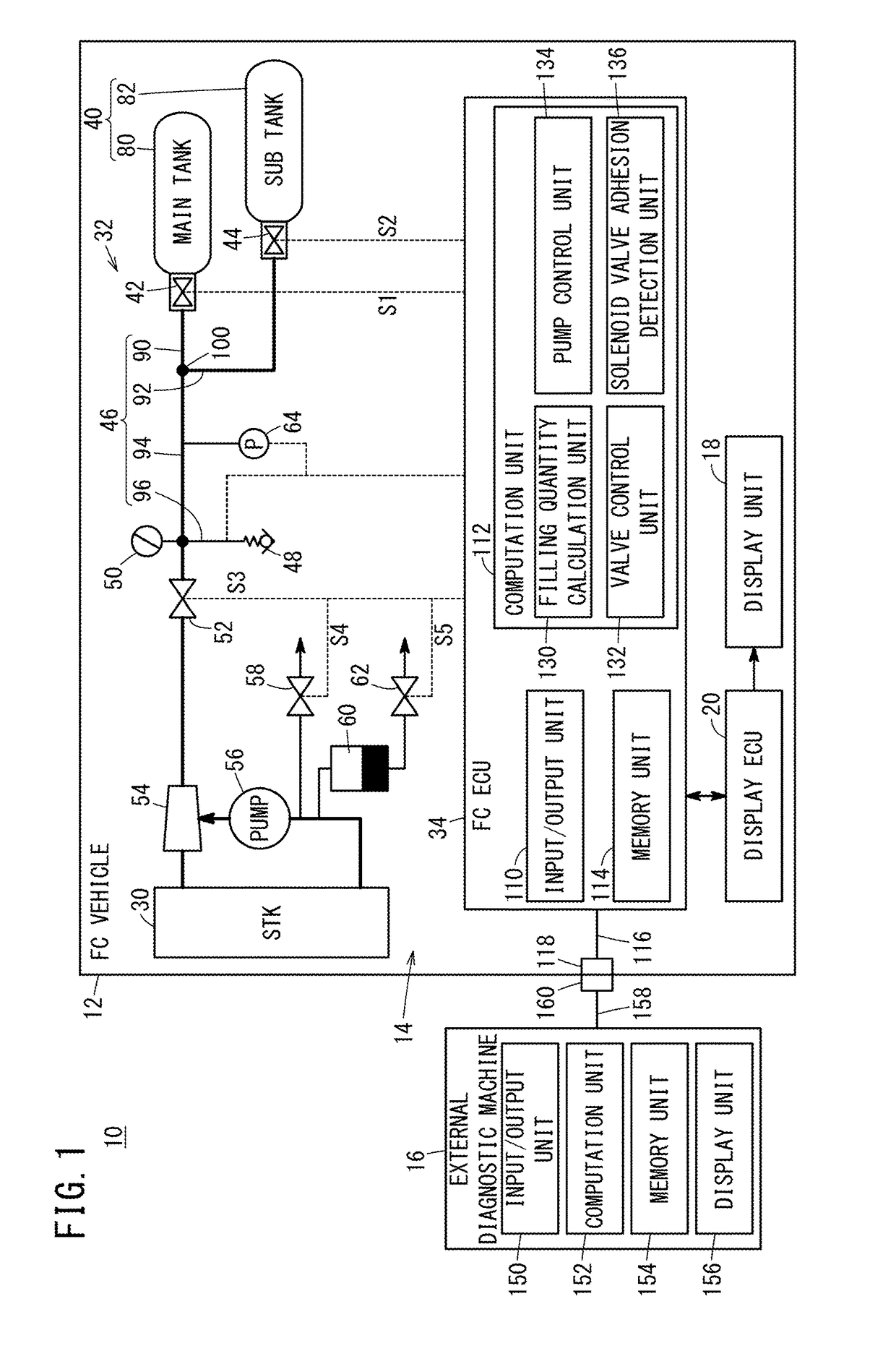
[0030]FIG. 1 is a diagram schematically showing overall structure of a fuel cell system 10 (hereinafter referred to as the “FC system 10”) according to an embodiment of the present invention. As shown in FIG. 1, the FC system 10 includes a fuel cell vehicle 12 (hereinafter referred to as the “FC vehicle 12” or the “vehicle 12”) equipped with a fuel cell unit 14 (hereinafter also referred to as the “FC unit 14”), and an external diagnostic machine 16. In addition to the fuel cell unit 14, the FC vehicle 12 includes a traction motor (not shown), a high voltage battery (not shown), a display unit 18, and a display electronic control unit 20 (hereinafter referred to as the “display ECU 20”), etc.

[0031]The FC unit 14 includes a fuel cell stack 30 (hereinafter referred to as the “FC stack 30”, the “fuel cell 30”, or the “FC 30”), an anode system 32, a cathode system (not shown), and an FC electronic control device 34 (hereinafter referred to as the “...


PUM

PropertyMeasurementUnit
poweraaaaaaaaaa
volumeaaaaaaaaaa
total volumeaaaaaaaaaa

Abstract

In a fuel cell system, an adhesion detection apparatus for detecting adhesion of a second switching valve for a sub tank is provided. The adhesion detection apparatus opens a first switching valve and a second switching valve for switching to a double switching valve open state where a fuel cell performs power generation, and thereafter, closes the first switching valve and opens the second switching valve for switching to a second switching valve open state where the fuel cell performs power generation, and detects adhesion of the second switching valve based on a change of a detection value of a pressure sensor in the second switching valve open state.

Description

CROSS-REFERENCE TO RELATED APPLICATION[0001]This application is based upon and claims the benefit of priority from Japanese Patent Application No. 2016-045123 filed on Mar. 9, 2016, the contents of which are incorporated herein by reference.BACKGROUND OF THE INVENTION[0002]Field of the Invention[0003]The present invention relates a method of inspecting a fuel cell system including a main tank and a sub tank for storing a fuel gas in which it is possible to detect adhesion of a switching valve (open / close valve) for the sub tank. Further, the present invention relates to the fuel cell system.[0004]Description of the Related Art[0005]Japanese Laid-Open Patent Publication No. 2004-095425 (hereinafter referred to as “JP2004-095425A”) has an object of providing a failure diagnostic system for a supply switching valve (open / close valve) in which it is possible to quickly perform failure diagnosis of the supply switching valve at the time of start-up operation ([0004] and Abstract). In ord...

Claims


Application Information

Patent Timeline
Patent Type & Authority Applications(United States)
IPC IPC(8): H01M8/04664H01M8/0438H01M8/04082
CPCH01M8/04664H01M8/0438H01M8/04201H01M8/04H01M8/04679H01M8/04089H01M8/04388Y02E60/50Y02T90/40
Inventor HOSOI, MASAKIOHARA, HIROKAZUMATSUMOTO, YUJI
Owner HONDA MOTOR CO LTD
Why Eureka
Try Eureka