

Efficient Fan Controller
a fan controller and efficient technology, applied in the field of efficient fan controllers, can solve the problems of reducing efficiency, affecting the efficiency of heating or cooling systems, affecting the efficiency of cooling systems, etc., and achieve the effects of improving efficiency, reducing costs, and operating more efficiently
- Summary
- Abstract
- Description
- Claims
- Application Information
AI Technical Summary
Benefits of technology
Problems solved by technology
Method used
Image

Examples
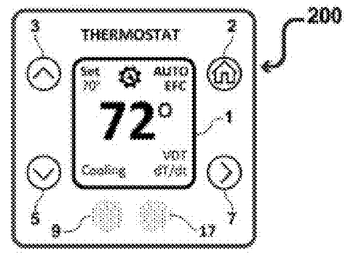
embodiment 200
[0159]If the length of the heat-source operational time P3 or cool-source operational time P4 are less than 4 minutes, then the thermostat embodiment can determine whether or not the system has a short cycling fault and display fault alarm information on the thermostat device or on a software application on an electronic device, cell phone, internet, or computer system to alert a user about the cooling or heating system not operating properly based on short cycling. The present invention thermostat embodiment 200 can also correct short cycling faults due to low differential (3 or a short-cycle cooling operational time P4 to lengthen subsequent operational times to improve thermal comfort and energy efficiency.
[0160]An air conditioner can turn on and off frequently or short cycle if it is oversized or if its thermostat has low hysteresis (<0.5° F.) or if its thermostat is located near a register or if it has the following faults: low airflow due to blocked or dirty air filters, faile...
PUM
 Abstract
Description
Claims
Application Information