Supercharge Your Innovation With Domain-Expert AI Agents!

Dust mitigation system utilizing conductive fibers

Active Publication Date: 2017-09-28
THE BOEING CO
View PDF0 Cites 13 Cited by
  • Summary
  • Abstract
  • Description
  • Claims
  • Application Information

AI Technical Summary

Benefits of technology

The Dust Mitigation System (DMS) is a device that reduces dust on surfaces. It includes a fabric material with conductive fibers embedded in it. When an alternating current is applied to the fabric, the conductive fibers generate an electric field on the surface of the fabric. This electric field creates a traveling wave that moves along the surface of the fabric, which helps to remove dust. The DMS can be used in various applications to reduce dust and improve air quality.

Problems solved by technology

This dust had caused several anomalies during the Apollo missions because of the lunar dust's strong tendency to collect on, adhere to, or otherwise contaminate the surface of equipment that were utilized in extravehicular activity (“EVA”) operations.
Additionally, the Apollo mission also exposed the ability of lunar dust to rapidly degrade spacesuits and impact the mission operations.
These effects included: 1) dust adhering and damaging spacesuit fabrics and system 2) mechanical problems associated to lunar dust that included problems with fittings and abrasion of suit layers causing suit pressure decay 3) vision obscuration; 4) false instrument readings due to dust clogging sensor inlets; 5) dust coating and contamination causing thermal control problems; 6) loss of traction; 7) clogging of joint mechanisms; 8) abrasion; 9) seal failures; and 10) inhalation and irritation.
Unfortunately, applying these technologies for spacesuit dust removal have remained a challenge due to the complexity of spacesuit design that includes irregular contours of the spacesuit, flexible structure of the soft areas of the spacesuit and polytretrafluroethylene (as an example, TEFLON® produced by The Chemours Company of Wilmington, Del.) coated spacesuit material.

Method used


Image

  • Dust mitigation system utilizing conductive fibers
  • Dust mitigation system utilizing conductive fibers
  • Dust mitigation system utilizing conductive fibers

Examples


Embodiment Construction

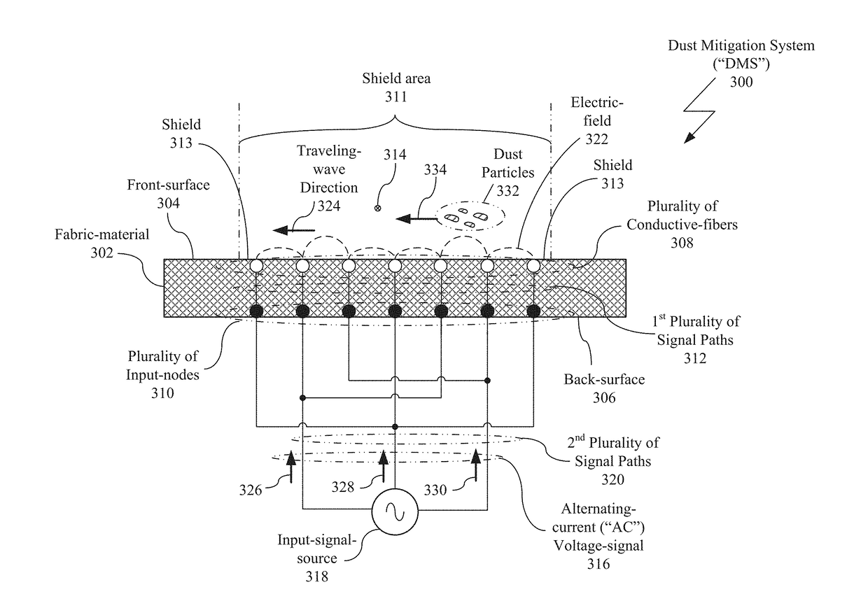
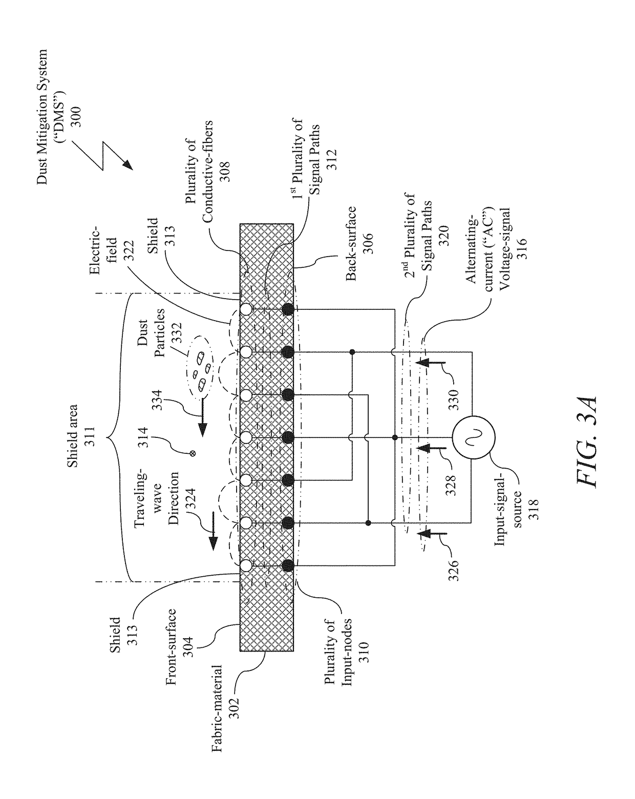
[0042]Disclosed is a Dust Mitigation System (“DMS”). The DMS includes: a fabric-material having a front-surface and a back-surface; a plurality of conductive-fibers within the fabric-material; and a plurality of input-nodes approximately adjacent to the fabric-material. The plurality of conductive-fibers are approximately parallel in a first direction along the fabric-material and are approximately adjacent to the front-surface of the fabric-material and the plurality of input-nodes are in signal communication with the plurality of conductive-fibers and configured to receive an alternating-current (“AC”) voltage-signal from an input-signal-source. The plurality of conductive-fibers are configured to generate an electric-field on the front-surface of the fabric-material in response to the plurality of input-nodes receiving the AC voltage-signal from the input-signal-source and a traveling-wave (of the electric-field) that travels along the front-surface of the fabric-material in a se...


PUM


Abstract

A Dust Mitigation System (“DMS”) is disclosed that includes a fabric-material having a front-surface and a back-surface; a plurality of conductive-fibers within the fabric-material; and a plurality of input-nodes approximately adjacent to the back-surface or the front-surface of the fabric-material. The plurality of conductive-fibers are approximately parallel in a first direction along the fabric-material and are approximately adjacent to the front-surface of the fabric-material and the plurality of input-nodes are in signal communication with the plurality of conductive-fibers and configured to receive an alternating-current (“AC”) voltage-signal from an input-signal-source. The plurality of conductive-fibers are configured to generate an electric-field on the front-surface of the fabric-material in response to the plurality of input-nodes receiving the AC voltage-signal from the input-signal-source and a traveling-wave (from the electric-field) that travels along the front-surface of the fabric-material in a second direction that is transverse to the first direction.

Description

CROSS-REFERENCE TO RELATED APPLICATION AND CLAIM OF PRIORITY[0001]The present patent application claims priority under 35 U.S.C. §119(e) to earlier filed U.S. provisional patent application No. 62 / 312,931, filed on Mar. 24, 2016, and titled “Dust Mitigation System Utilizing Carbon Nanotube Fibers,” which is hereby incorporated by reference in its entirety.BACKGROUND[0002]1. Field[0003]The present disclosure relates to dust mitigation, and more, particularly to a dust mitigation system utilizing conductive-fibers.[0004]2. Related Art[0005]Exploration activities preformed on the Moon by both humans and robotic spacecraft occur on a planetary surface that is comprised of unconsolidated fragmental rock material known as the lunar regolith. The lunar surface is covered by several layers of thick regolith formed by high-velocity micrometeoroid impacts, and is characterized by the steady bombardment of charged atomic particles from the sun and the stars. The lunar regolith includes rock fr...

Claims


Application Information

Patent Timeline
IPC IPC(8): B03C3/06B03C3/60B03C3/41
CPCB03C3/06B03C3/60B03C3/41B03C7/026B08B7/02B08B17/02B64G6/00B64G1/44B64G1/52B64G1/66B64G99/00
Inventor MANYAPU, KAVYA K.PELTZ, LEORA
Owner THE BOEING CO
Features
  • R&D
  • Intellectual Property
  • Life Sciences
  • Materials
  • Tech Scout
  • Unparalleled Data Quality
  • Higher Quality Content
  • 60% Fewer Hallucinations
Learn More