Hydrocarbon-water separator

a technology of hydrocarbon separator and separator tank, which is applied in the direction of separation process, separation process, and treatment water, etc., can solve the problems of limited space available for separator tanks aboard ships or offshore platforms, large input fluid rate, and high cost, so as to reduce manufacturing costs and improve flow conditions

Active Publication Date: 2017-09-28
STAUPER OFFSHORE AS
View PDF2 Cites 6 Cited by
  • Summary
  • Abstract
  • Description
  • Claims
  • Application Information

AI Technical Summary

Benefits of technology

[0014]In operation, an initial fluid contains dissolved gas, including process gas supplied upstream from the inlet. The tangentially mounted pipe assembly inside the conical shaped tank causes the fluid to rotate and rise within the annular space formed by the conical wall in a conventional manner. The conical bowl configuration (inlet chamber) with baffle plates at the upper part of the cone and the top mounted guide vanes convert the helical liquid flow from the lower part of the conical bowl into laminar and axial flow over the guide vanes. There will be no pulsation or oscillation of the liquid layers in the area between the position of the guide vanes and the outer tank wall. This greatly enhances the overall efficiency of the process. Water relieved from gas and oil at the upper end of the conical tank flows into the space between outer tank and the inner conical bowl and sinks towards the water outlet port at the bottom of the tank. Any debris, scale and small particles may be drained off through a separate pipe-connection attached to the bottom of the conical tank. The conical shaped area of the inner tank will provide an additional pressure drop thereby increasing the release of gas without affecting the upward rotating flow adversely.
[0016]The internal pressure in each conical bowl segment may be less than the pressure in any previous conical bowl segment. This allows for a gradual reduction of pressure, for example to or below atmospheric pressure, and may be useful to ensure efficient flow within each bowl segment over a large pressure differential from the first inlet to the last outlet. Additional supplies of process gas at each segment may not be required, as more gas is released from the fluid during each pressure drop.
[0018]In a preferred embodiment, the channels or pipes are mounted inside the conical wall segment and between the conical wall segment and the outer tank segment. This greatly improves the laminar flow control, the capacity per unit volume and, most significantly, the overall efficiency. There are no internal couplings, bolts and nuts an unwanted scales are removed by recognised chemicals. Adequate internal inspection is achieved via manholes. Gas supply, sensors, operating valves etc. are mounted at the inlet and outlet piping from the outer tank segment.
[0025]In a preferred embodiment with two or more conical wall segments the downward flowing marginally contaminated water may enter the following conical wall segment through a centre mounted vertical pipe, FIG. 7, thereby avoiding separate piping arrangements, (116) FIG. 1 and reducing manufacturing costs and improving flow conditions.

Problems solved by technology

Further, the rate of input fluid may be large, and the space available for a separator tank aboard a ship or in an offshore platform may be limited or costly.

Method used


Image

  • Hydrocarbon-water separator
  • Hydrocarbon-water separator
  • Hydrocarbon-water separator

Examples


Embodiment Construction

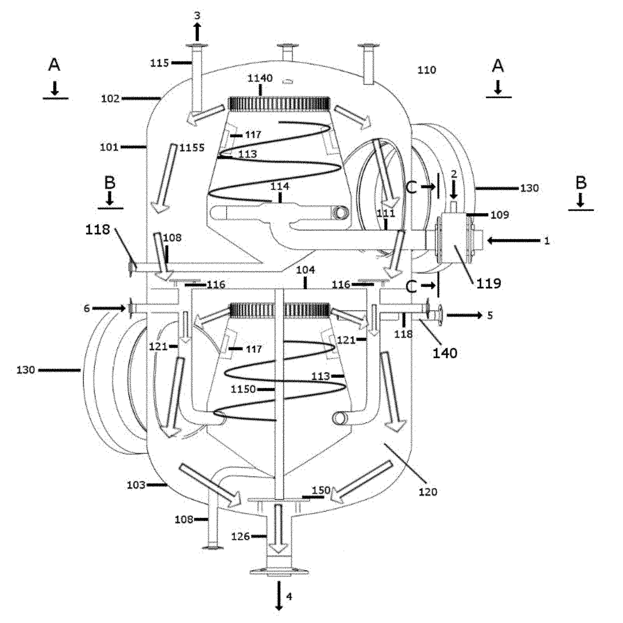
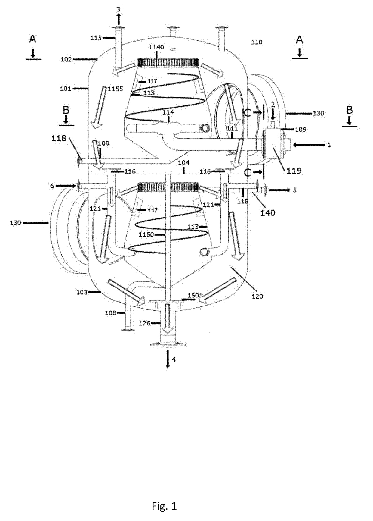
[0034]FIG. 1 illustrates an apparatus 100 according to the invention. The apparatus 100 comprises a cylindrical tank wall 101 closed by a top cap 102 and a bottom cap 103. An input flow of initial fluid 1 contains a mixture of water, hydrocarbons and a process gas 2, i.e. N2 or CO2. The process gas is thoroughly mixed with hydrocarbons and water in a mixer 109, and fed into a cone shaped bowl through a pipe which is split into two or more pipes, i.e. pipe spread, with pipe ends protruding tangentially to the inner conical wall forcing the fluid into an upward rotating laminar flow in a clockwise direction when viewed from above. This is advantageous on the northern hemisphere due to the Coriolis force and hence the natural direction of a vortex north of equator. Accordingly the pipe assembly designed for the southern hemisphere would preferably guide the input fluid in the opposite direction, i.e. counter-clockwise when viewed from above.

[0035]The upper part of the bowl comprises a ...


PUM

PropertyMeasurementUnit
pressureaaaaaaaaaa
internal pressureaaaaaaaaaa
pressureaaaaaaaaaa

Abstract

An apparatus for separating hydrocarbons from water, comprising a tank segment with a fluid inlet subsequent a housing with a liquid gas mixer. The fluid inlet through a cylindrical tank wall,and further through the wall of a conical wall segment, a pipe spread, combining radial and axial flow over ring mounted guide vanes at the upper part of the conical wall segment. A hydro carbon outlet is located at a top end and a water outlet at a bottom end of tank-segment. A pipe for scale and debris removal is connected to the lower part of the bowl. The inner conical wall segment extends to the top end of the tank segment and at this location comprises a ring of vertically mounted guide vanes.

Description

CROSS-REFERENCE TO RELATED APPLICATIONS[0001]This patent application claims the benefit of Norwegian Patent Application No. 20160495, filed Mar. 23, 2016, which is incorporated by reference.FIELD OF THE INVENTION[0002]The present invention concerns an apparatus for separating hydrocarbons and water, in particular of the kind using a process gas for lifting oil.BACKGROUND OF THE INVENTIONPrior and Related Art[0003]Separating hydrocarbons, i.e. oil and / or gas, and water is required in several applications. One typical example is separating oil from bilge water aboard a ship. Another example is separating oil and / or natural gas from a well fluid produced at an offshore oil or gas field. In both examples, the input fluid typically has a high content of water. Further, the rate of input fluid may be large, and the space available for a separator tank aboard a ship or in an offshore platform may be limited or costly.[0004]Hydro-cyclones and other fast liquid-liquid separators are known in...

Claims


Application Information

Patent Timeline
Patent Type & Authority Applications(United States)
IPC IPC(8): C02F1/24B01D19/00C02F1/20B01D17/02C02F1/40
CPCC02F1/24B01D17/0205C02F1/40C02F2103/008B01D19/00C02F2101/32C02F2103/10C02F1/20B01D17/0217B01D19/0057C02F2301/022C02F2301/026B01D19/0005B01D17/00B01D17/02B04C1/00B04C5/00B04C5/04B04C5/08B04C5/103B04C5/107E21B43/34E21B43/36B03D1/1418
Inventor FOLKVANG, JORN
Owner STAUPER OFFSHORE AS
Why Eureka
Try Eureka