
Injector having in-built ignition system

a technology of injector and ignition device, which is applied in the direction of spark plugs, machines/engines, mechanical equipment, etc., can solve the problems of reducing the outer diameter of the casing entirely, malfunctioning or damage of the actuator operating the needle of the injection nozzle such as electromagnetic coils and piezo elements, and the limitation of the outer diameter length of the ignition plug, so as to simplify the insulation structure in the path to the discharger and reduce the size of the configuration , the effect o

Inactive Publication Date: 2017-09-28
MAGINEERING INC
View PDF8 Cites 5 Cited by
  • Summary
  • Abstract
  • Description
  • Claims
  • Application Information

AI Technical Summary

Benefits of technology

The present invention provides an injector with a built-in ignition device that can be located in a compact way, even when other components are also present. This results in a smaller overall device size.

Problems solved by technology

However, in the injector incorporating the ignition device disclosed in Japanese unexamined patent application publication No.
H07-19142, there s a problem that the actuator for operating needle of the injection nozzle such as electromagnetic coil and piezo element, may be malfunctioned or damaged caused of influence of high voltage for the ignition plug used as the ignition device.
Further, since the injector incorporating the ignition device disclosed in Japanese unexamined patent application publications No. 2005-511966 and No. 2008-255837 is configured to arrange the fuel injecting device and the ignition plug used as the ignition device within one casing and the normal ignition plug is used, there was a problem that the outer diameter length of the ignition plug has limitation for reducing, then the outer diameter of the casing becomes large entirely, and it is difficult to secure space for attaching to the internal combustion engine.

Method used


Image

  • Injector having in-built ignition system
  • Injector having in-built ignition system
  • Injector having in-built ignition system

Examples


first embodiment

Injector Having Built-In Ignition Device

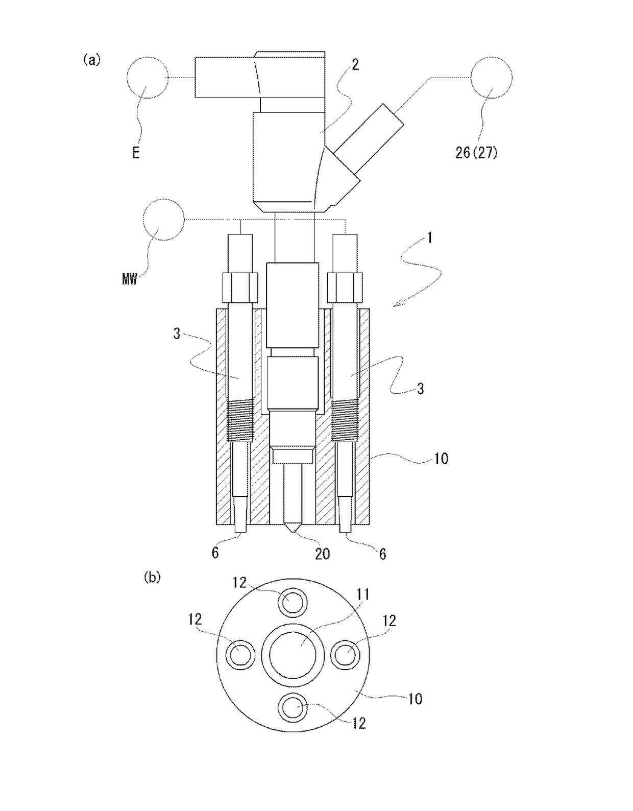
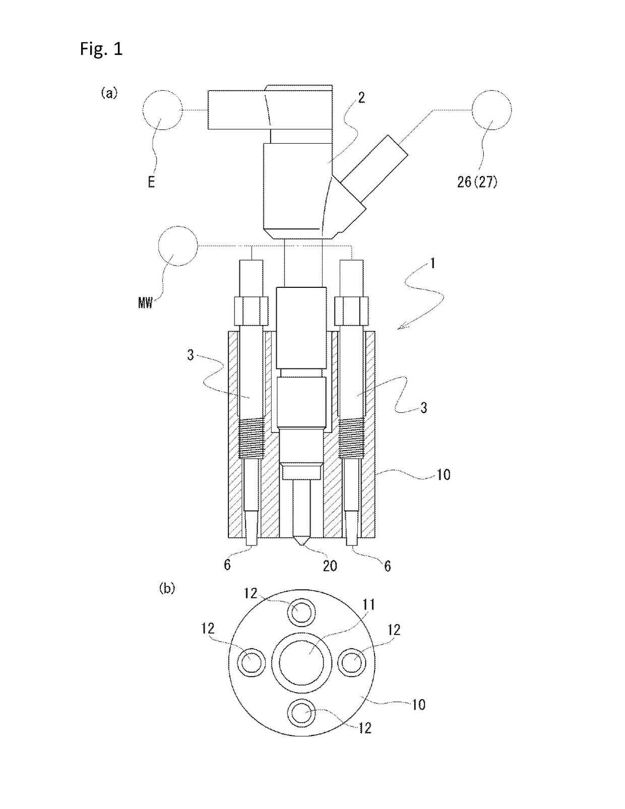
[0023]The present first embodiment is an injector 1 having a built-in ignition device regarding the present invention. The injector 1 having the built-in ignition device includes a fuel injecting device 2, a plasma generator 3 used as the ignition device, and a casing 10, as illustrated in FIG. 1.

[0024]As illustrated in FIG. 1(b), in the injector 1 having the built-in device, a mounting port 11 for mounting the fuel injecting device 2 in center of the cylindrical casing 10, and a plurality of mounting ports 1 (four locations in the present embodiment) for mounting the plasma generators 3 surrounding the mounting port 11 and concentrically with the axial center of the mounting port 11, are opened on the cylindrical casing 10. Fixing means of the fuel injecting device 2 and the plasma generators 3 towards the mounting ports 11, 12 is t especially limited, sealing member is interposed between them, male screw parts engraved on the outer surfaces ...


PUM


Abstract

A small-size injector having a built-in ignition device which can surely inject fuel and ignite the fuel with low electric power by the ignition device with a simple configuration is provided. The injector comprises a fuel injecting device 2 having a fuel injecting port 20 that injects the fuel, an ignition device 3 configured to ignite the injected fuel, and a casing 10 inside housing therein the fuel injecting device 2 and the ignition device 3 together. The motion device 3 is constituted of a plasma generator 3 which integrally comprises a booster 5 having a resonation structure capacity-coupled with an electromagnetic wave oscillator MW configured to oscillate an electromagnetic wave, and a discharger 6 configured to cause a discharge of a high voltage generated by the booster 5.

Description

TECHNICAL FIELD[0001]The present invention relates to an injector having a built-in ignition device.PRIOR ART[0002]Various injectors incorporated with ignition plug are suggested as injectors incorporating ignition device. These are expected for use to direct-inject-type-engines with regard to diesel engines, gas engines, and gasoline engines. Injectors incorporating ignition device are classified broadly into those having coaxial structure in which the axial center of injector (fuel injecting device) is aligned with the axial center of the central electrode of ignition plug used as ignition device, and those of accommodating fuel injecting device and ignition device within a casing by aligning in parallel. The coaxial structure type is disclosed in, for example, Japanese unexamined patent application publication No. H07-71343, and Japanese unexamined patent application publication No. H07-19142, With regard to the injector incorporating the ignition device, the central electrode of...

Claims


Application Information

Patent Timeline
Patent Type & Authority Applications(United States)
IPC IPC(8): F02M57/06F02P23/04H01T13/44F02P3/01
CPCF02M57/06H01T13/44F02P23/04F02P3/01F02P13/00H01T13/40F02P15/006F02P15/02F02P23/045
Inventor IKEDA, YUJIMAKITA, MINORU
Owner MAGINEERING INC
Learn More