Organic el display unit, method of manufacturing the same, and electronic apparatus

a technology of electroluminescence and display unit, which is applied in the direction of electric lighting source, solid-state device, and light source, can solve the problems of difficult narrowing of the bezel region, and achieve the effects of reducing the bezel portion, large size, and impairing the reliability of the organic el display uni

Active Publication Date: 2017-09-28
SONY CORP
View PDF2 Cites 29 Cited by
  • Summary
  • Abstract
  • Description
  • Claims
  • Application Information

AI Technical Summary

Benefits of technology

[0098]In the display unit 1, a scanning signal is supplied from the scanning line drive circuit 130 to each pixel 5 through the gate electrode of the write transistor Tr2, and an image signal is supplied from the signal line drive circuit 120 through the write transistor Tr2 to a holding capacitor Cs and is stored therein. In other words, the drive transistor Tr1 is on / off controlled depending on the signal stored in the holding capacitor Cs. This causes a drive current Id to be injected into the organic EL device 10, and thus holes and electrons are recombined to generate light emission. The light is transmitted through the counter electrode 29, the protective film 30, the adhesive layer 40, unillustrated color filters of respective colors, and the counter substrate 31 to be extracted, because the display unit 1 is a top surface emission (top emission) display unit in this example. In a manner as described above, the display unit 1 performs image display (color image display).
[0099]Incidentally, an organic EL display unit used, for example, as an organic EL television is requested to enlarge an effective display region as a measure to seek a design property as described above, and thus is requested to reduce a bezel portion. However, simply narrowing the bezel region causes entering of moisture from the outside, thus deteriorating organic layers configuring the light-emitting device. This causes a non-emission region referred to as “dark spot” to be formed, which impairs the reliability of the organic EL display unit.
[0100]In order to solve this issue, it is necessary, for example, to allow an organic insulating film such as a flat film provided around the emission region and a so-called sealing layer that performs surface-sealing of a gap between substrates to have a certain degree of width. Further, an organic insulating film formed to have a relatively large size for suppressing entering of, for example, moisture from the outside causes moisture remaining in the film to be increased accordingly. Thus, it is contemplated that formation of a separating groove that separates the organic insulating film into an inner peripheral portion and an outer peripheral portion suppresses entering of moisture contained in the organic insulating film.
[0101]However, it is difficult for the above-described method to reduce the bezel region sifnificantly, although the method is able to prevent or suppress the entering of moisture into the organic layer.
[0102]In contrast, unlike the example of providing a structure that suppresses the entering of moisture into the peripheral region 110B on the periphery of the display region 110A, the display unit 1 of the present embodiment is configured to provide the sealing structure 50 on the end surface of the display panel formed by joining the drive substrate 11 and the counter substrate 31 together, with the display layer 20 including the organic EL device 10 being interposed therebetween. In particular, by configuring the sealing structure 50 as layered films of the inorganic film 51 made of an inorganic material and the organic film 52 made of an organic material, it becomes possible to minimize the sealing structure that suppresses the entering of moisture into the display layer 20. This enables the bezel region to be 0.1 mm or smaller, for example.
[0103]In the present embodiment, the sealing section 50 is provided on the end surface of the display layer 20 including the organic layer 28 provided between the drive substrate 11 and the drive substrate 11 as described above. The sealing section 50 is so provided as to overlap at least a portion of the end surfaces of the drive substrate 11 and the drive substrate 11. This makes it possible to prevent the entering of moisture into the organic layer 28 while reducing the peripheral region 110B provided on the periphery of the display region 110A as much as possible. Thus, it becomes possible to provide the display unit 1 that has a narrow bezel region while keeping reliability, and an electronic apparatus including the display unit 1.

Problems solved by technology

This makes it difficult to narrow the bezel region, because it is necessary for the gas barrier layer that covers the organic layer to be formed larger than the run-off portion of the organic layer.

Method used


Image

  • Organic el display unit, method of manufacturing the same, and electronic apparatus
  • Organic el display unit, method of manufacturing the same, and electronic apparatus
  • Organic el display unit, method of manufacturing the same, and electronic apparatus

Examples


application example (

3. Application Example (An application example to an electronic apparatus)

embodiment

1. Embodiment

(1-1. Overall Configuration)

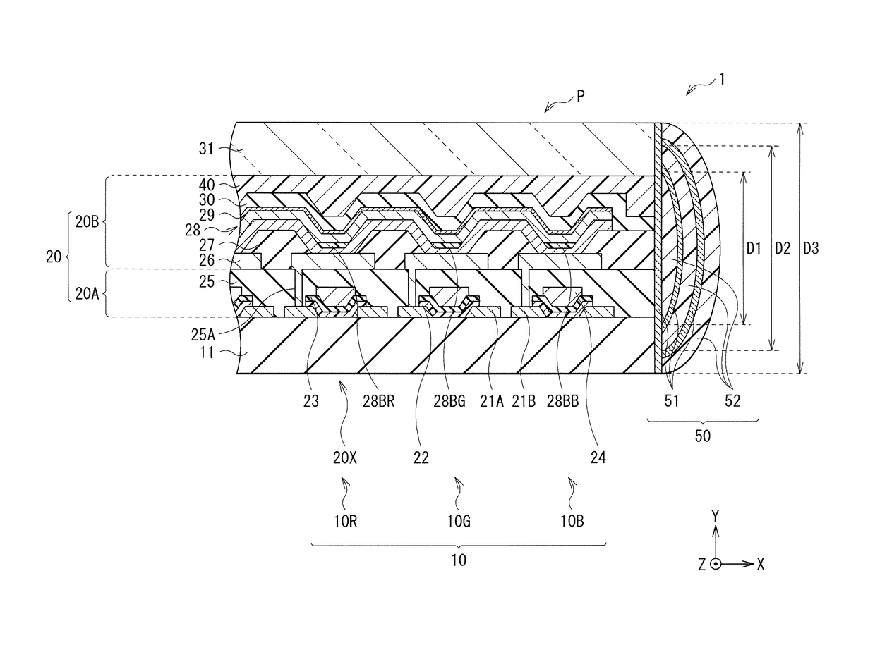
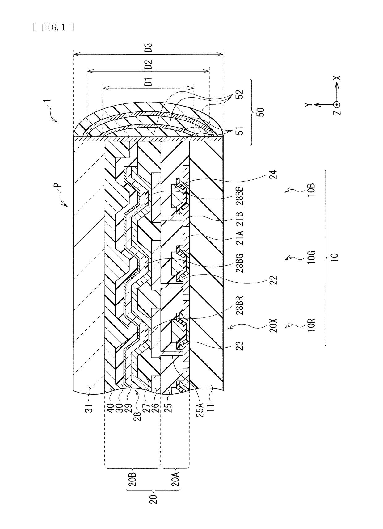
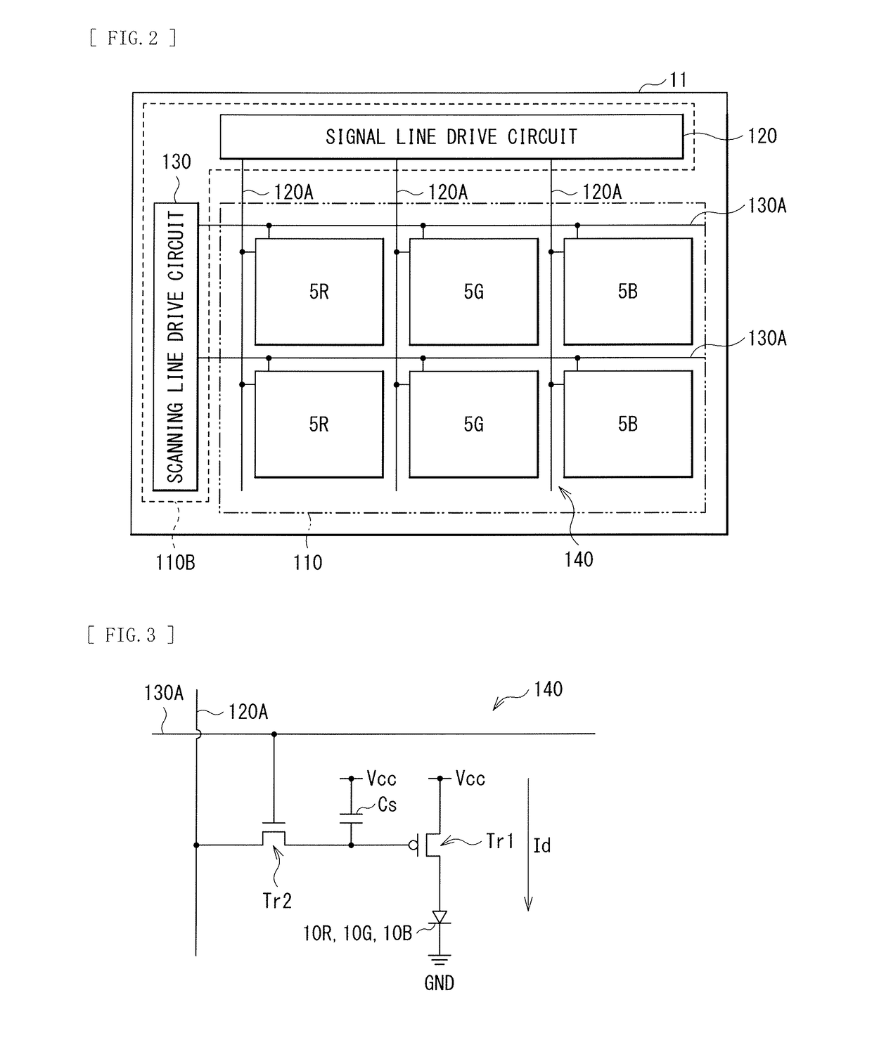
[0044]FIG. 1 illustrates a cross-sectional configuration of an organic EL display unit (display unit 1) according to an embodiment of the present disclosure. The display unit 1 is used as an organic EL television, for example. The display unit 1 includes a drive substrate 11 on which there are provided a display region 110A and a peripheral region 110B on the periphery of the display region 110A (see FIG. 2). The display unit 1 is, for example, a top surface emission (so-called top emission) display unit. The top surface emission display unit uses, as light-emitting devices, an organic EL device 10 that emits any of color light beams of R (red), G (green), and B (blue) (a red organic EL device 10R, a green organic EL device 10G, a blue organic EL device 10B), and the color light beams are emitted from top surface side (side opposite to the drive substrate 11). The display unit 1 according to the present embodiment includes a display layer 20 ...

modification example

2. Modification Example

[0104]Now, modification examples (Modification Examples 1 to 3) of the foregoing embodiment are described. It is to be noted that the same reference numeral is assigned to the same component in the foregoing embodiment, and description therefor is omitted where appropriate.


PUM


Abstract

An organic EL display unit includes a first substrate, a second substrate, a display layer, and a sealing section. The display layer is provided between the first substrate and the second substrate. The display layer includes an organic layer. The sealing section is provided continuously from an end surface of the display layer to at least a portion of respective end surfaces of the first substrate and the second substrate.

Description

TECHNICAL FIELD[0001]The present disclosure relates to an organic electroluminescence (EL) display unit that emits light utilizing an organic EL phenomenon, a method of manufacturing the organic EL display unit, and an electronic apparatus including the organic EL display unit.BACKGROUND ART[0002]Small-sized to mid-sized display units used for portable devices such as smartphones and tablet terminals have been requested to have a high-definition display performance with low power consumption and to have a thin and light-weight design property. As the display units that meet these requests, a display unit with use of an organic light-emitting device (OLED), i.e., an organic EL display unit has attracted attentions. The organic EL display unit is a self-luminous display unit, and thus has a wide viewing angle and does not necessitate a backlight. Therefore, the organic EL display unit has features such as low power consumption, responsiveness, and decrease in thickness of the display ...

Claims


Application Information

Patent Timeline
Patent Type & Authority Applications(United States)
IPC IPC(8): H05B33/22H01L51/52H01L27/32
CPCH05B33/22H01L27/3206H01L27/3209H01L27/3244H01L51/5256H10K59/12H10K50/8445H10K50/8426H10K59/30H10K59/32
Inventor TADA, KEISHIYAMADA, JIROMORIKAWA, SHINICHIROSEKINE, MASAAKIMATSUSHITA, NAOKIHANAWA, KOHJI
Owner SONY CORP
Why Eureka
Try Eureka