
Angulated dental implant

a dental implant and abutment technology, applied in dental implants, dental surgery, medical science, etc., can solve the problems of angled dental implants being not typically suitable for abutments, prone to breakage/snap/fail, and complicated abutments

Active Publication Date: 2017-10-05
SOUTHERN IMPLATS (PTY) LTD
View PDF8 Cites 20 Cited by
  • Summary
  • Abstract
  • Description
  • Claims
  • Application Information

AI Technical Summary

Benefits of technology

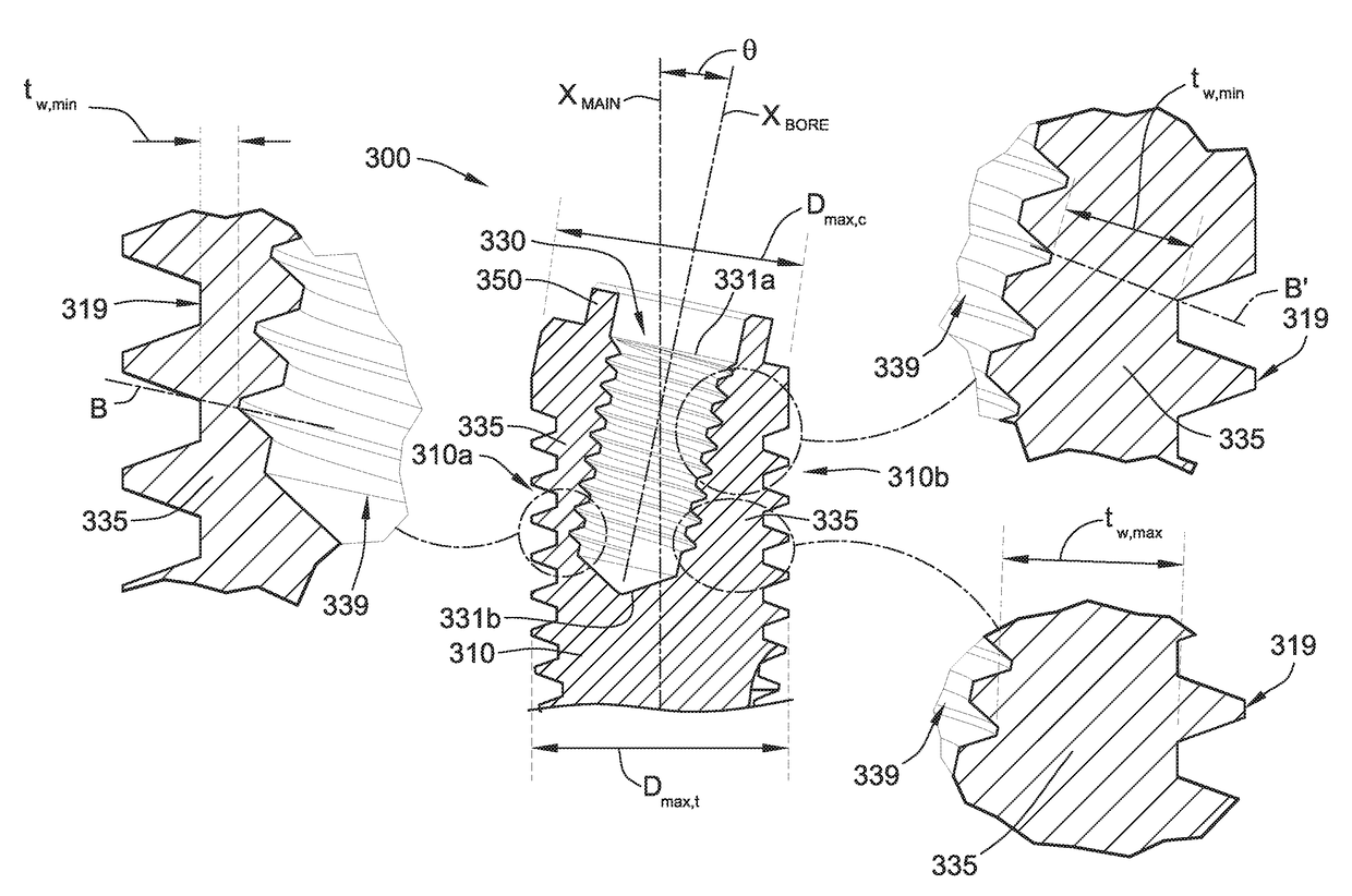
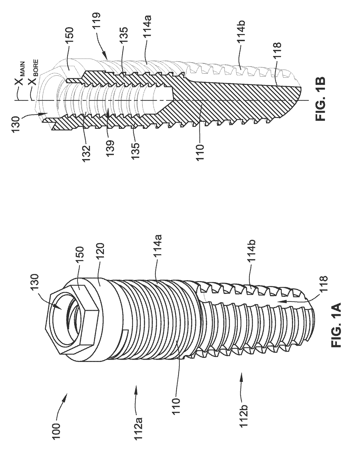
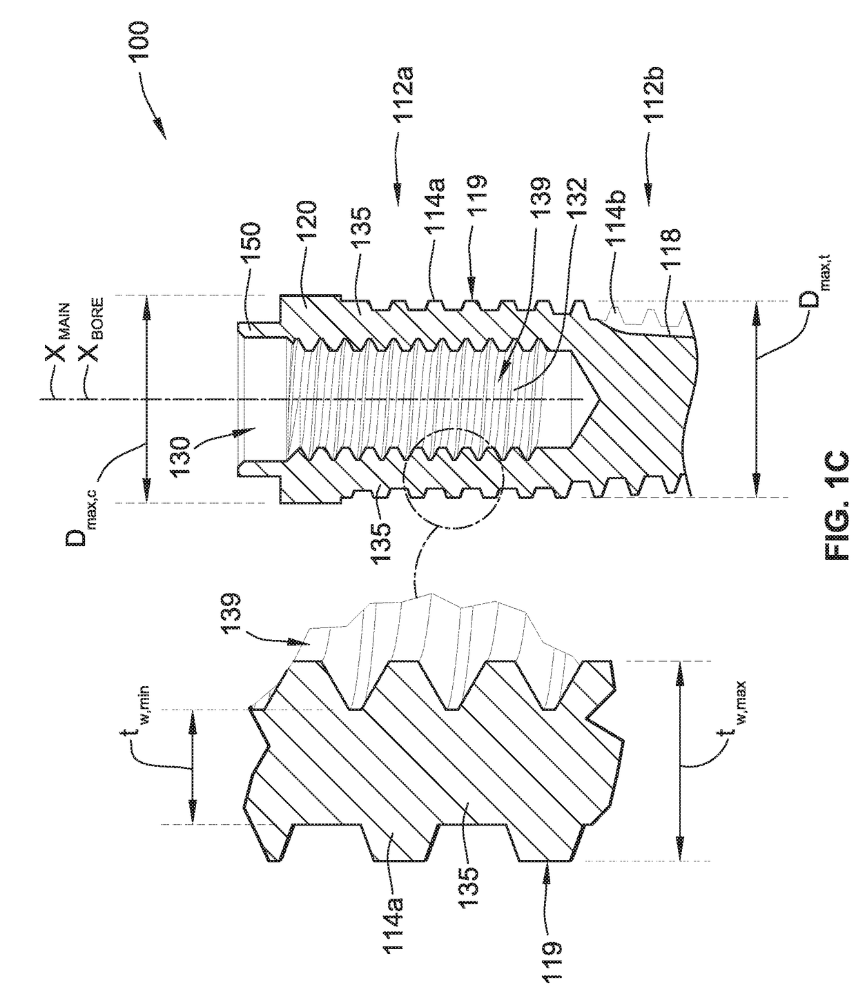
The present patent describes dental implants with a non-rotational feature that engages the abutment in a non-rotational fashion. The non-rotational feature is formed in the interior of the implant and is designed to prevent rotation of the abutment when it is engaged with the implant. The dental implants are made from cold-worked, high strength, commercially pure titanium and have a maximum outer diameter of at least about 900 MPa. The interior of the implant has a bore-central axis that is at an angle between about 40° and about 65° relative to the main-central axis of the implant. The non-rotational feature is engaged with the abutment in a non-rotational fashion and is designed to prevent rotation of the abutment when it is engaged with the implant. The ratio of the maximum outer diameter of the implant to the thinnest portion of the interior wall is between about 50 and about 75. The technical effect of the non-rotational feature is improved stability and secure anchoring of the abutment in the dental implant.

Problems solved by technology

This latter scenario can be more complicated due to the added connection between the dental implant and the abutment.
As such, if the outer diameter is too small (even if just at a relatively small portion of the angled dental implant), the angled dental abutment may be prone to easily break / snap / fail.
Due to these limitations, angled dental implants have typically been limited to having at least a 4.5 millimeter outer diameter; however, such angled dental implants are not typically suitable for use in the anterior maxilla / mandible as the anterior maxilla / mandible in many patients is not able to support dental implants with such a large outer diameter.

Method used


Image

  • Angulated dental implant
  • Angulated dental implant
  • Angulated dental implant

Examples


Embodiment Construction

[0038]The dental implants of the present disclosure described herein are formed from (e.g., machined out of) cold-worked, high strength, commercially pure titanium having an ultimate tensile strength of at least about 900 megapascals (MPa). Ultimate tensile strength it is meant to refer to the maximum stress that a material can withstand while being stretched or pulled before breaking. By cold-worked, it is meant that the material is shaped at a temperature below its recrystallization temperature (e.g., ambient temperature). Examples of such shaping techniques include: squeezing, bending, drawing, shearing, rolling, or any combinations thereof.

[0039]In some implementations, the dental implants of the present disclosure are formed from cold-worked, high strength, commercially pure titanium having an ultimate tensile strength of at least about 900 megapascals (MPa). The material used to make the dental implants of the present disclosure starts as commercially pure titanium (e.g., Grad...


PUM


Abstract

A dental implant includes a generally cylindrical body, an interior bore, and a non-rotational feature. The generally cylindrical body has a main-central axis and is formed from cold-worked, high strength, commercially pure titanium having an ultimate tensile strength of at least about 900 MPa. The generally cylindrical body has a proximal portion and an opposing distal portion for anchoring the dental implant in bone of a patient. The interior bore is formed in the generally cylindrical body and has (i) a bore-central axis and (ii) a threaded portion for receiving a screw that is configured to removable hold an abutment in engagement with the dental implant. The non-rotational feature is configured to engage the abutment in a non-rotational fashion.

Description

CROSS-REFERENCE TO RELATED APPLICATIONS[0001]This application claims the benefit of and priority to U.S. Provisional Application No. 62 / 315,274, filed Mar. 30, 2016, and U.S. Provisional Application No. 62 / 361,665, filed Jul. 13, 2016, each of which is hereby incorporated by reference herein in its entirety.TECHNICAL FIELD[0002]This disclosure relates to restorative dental implants and abutments and more specifically to dental implants formed from cold-worked, high strength, commercial pure titanium.BACKGROUND[0003]Single tooth restorations (e.g., crowns) present the unique requirement that they must be supported non-rotationally on an underlying structure (e.g., a natural tooth prep, an abutment / implant assembly, etc.). When the underlying structure is a prepared natural tooth, this non-rotational supporting requirement is met in the normal course of preparing the natural tooth with a non-circular cross-section. Similarly, when the underlying structure is an abutment secured to a d...

Claims


Application Information

Patent Timeline
Patent Type & Authority Applications(United States)
IPC IPC(8): A61C8/00
CPCA61C8/0056A61C8/0054A61C8/0068A61C8/006A61C8/0037A61C8/0025A61C8/0074A61C8/0034A61C8/0089A61C8/0022
Inventor BLACKBEARD, GRAHAM ALANCUMMING, LEITH CARRUTHERS
Owner SOUTHERN IMPLATS (PTY) LTD
Learn More