Glass bonding material and multilayer glass

a multi-layer glass and glass bonding technology, applied in the direction of building components, metal-working apparatus, construction, etc., can solve the problems of large thermal expansion difference, cracks, breakages, etc., and achieve the effect of suppressing cracks, suppressing peeling of glass bonding materials, and suppressing peeling of glass

Active Publication Date: 2017-10-05
HITACHI METALS LTD
View PDF4 Cites 0 Cited by
  • Summary
  • Abstract
  • Description
  • Claims
  • Application Information

AI Technical Summary

Benefits of technology

[0029]The multilayer glass according to the second aspect of the present invention is a multilayer glass formed by arranging a plurality of glass plates with a gap therebetween and bonding a plurality of glass plates by a sealing part, and the sealing part includes a glass bonding material made of a cladding material in which at least a first layer made of an Al-based alloy and configured to be bonded to glass and a second layer made of an Fe—Ni based alloy having a thermal expansion coefficient from 30° C. to 400° C. of 11.5×10⁻⁶ (K−1) or less are bonded. With this structure, using the glass bonding material capable of suppressing peeling from the glass while suppressing the occurrence of cracks, breakages, etc., in the fritted glass, a multilayer glass in which a plurality of glass plates are bonded together with the gap therebetween can be obtained.
[0030]In the multilayer glass according to the second aspect, it is preferable that the sealing part be formed by bonding the fritted glass and the glass bonding material. With this structure, it is possible to suppress peeling of the glass bonding material from the fritted glass while suppressing the occurrence of cracks, breakages, etc., in the fritted glass. Further, when bonding a plurality of glass plates and the fritted glass of the sealing part, since the fritted glass melts at a low temperature, it is possible to easily form the bonding between the glasses and suppress peeling of the sealing part and the glass plate.
[0031]In the multilayer glass according to the second aspect, it is preferable that the gap be lowered in pressure. With this structure, in the multilayer glass in which peeling of the glass bonding material from the glass is suppressed, it is possible to reduce the thermal conductivity in the gap between the glass plates, and therefore it is possible to improve the heat insulating performance.
[0032]According to the present invention, as described above, it is possible to provide a glass bonding material having a configuration capable of suppressing occurrence of peeling of the glass bonding material from glass while suppressing the occurrence of cracks, breakages, etc., in the glass due to the glass bonding material while coping with the type of glass to be bonded, and also to provide a multilayer glass using the glass bonding material.

Problems solved by technology

However, the present inventors have found a problem that when an Al plate and fritted glass are bonded, a large thermal expansion difference occurs between the Al plate and the fritted glass or the soda-lime glass plate due to the large thermal expansion coefficient of the Al plate, which may cause cracks, breakages, etc., in the fritted glass due to the large thermal stress due to the thermal expansion difference.
In addition, the present inventors found the fact that when a low expansion plate material such as an Fe-42Ni-6Cr alloy plate material or an Fe-50Ni alloy plate material and fritted glass are bonded, the peeling strength (peel strength) between the fritted glass and the low expansion plate material is small, causing a problem that the low expansion plate material is likely to be peeled off from the fritted glass.

Method used


Image

  • Glass bonding material and multilayer glass
  • Glass bonding material and multilayer glass
  • Glass bonding material and multilayer glass

Examples


first embodiment

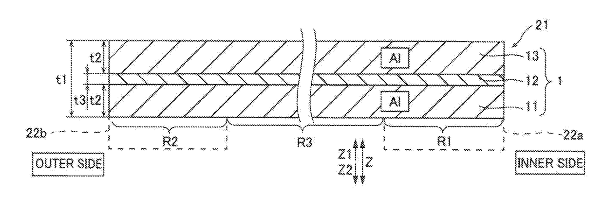
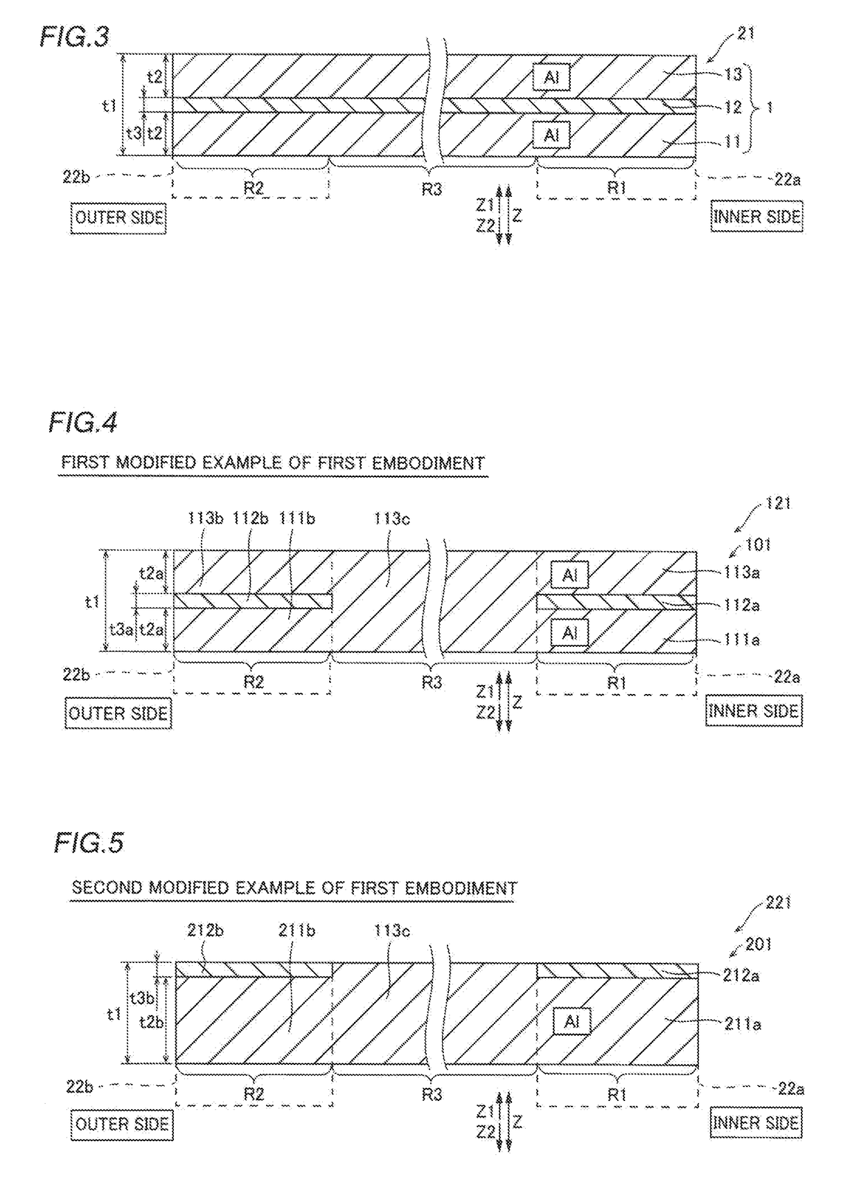
[0050]First, the configuration of a vacuum multilayer glass 100 according to a first embodiment of the present invention will be described with reference to FIGS. 1 to 3. Note that the vacuum multilayer glass 100 is an example of the “multilayer glass” according to the present invention.

[0051]The vacuum multilayer glass 100 according to the first embodiment of the present invention is provided with, as shown in FIG. 1 and FIG. 2, two glass plates 10a and 10b arranged so as to face with each other with a predetermined gap S1 therebetween and a sealing member 20 arranged at the sealing part A (peripheral region) provided at the entire circumference of the peripheral portion of the vacuum multilayer glass 100 for sealing the glass plate 10a and the glass plate 10b with the gap S1 therebetween. The length (distance D1) between the glass plate 10a and the glass plate 10b in the thickness direction (Z direction) of the gap S1 is about 200 μm. Also, the sealing member 20 includes an approx...

first modified example of first embodiment

[0094]Next, a first modified example of the first embodiment of the present invention will be described with reference to FIG. 4. In this first modified example of the first embodiment, unlike the first embodiment in which the reinforcing member 21 is made of an overlay type cladding material 1, an embodiment in which core layers 112a and 112b of a reinforcing member 121 are arranged only at positions facing the bonding regions R1 and R2 will be described. The reinforcing member 121 is one example of the “glass bonding material” made of the cladding material 101 according to the present invention.

[0095]As shown in FIG. 4, the reinforcing member 121 according to the first modified example of the first embodiment of the present invention is configured by a cladding material 101 in which a three-layer structure is formed only in the bonding regions R1 and R2 and a single layer structure (no layer structure is formed) is formed in the region other than the bonding regions R1 and R2.

[009...

second modified example of first embodiment

[0105]Next, a second modified example of the first embodiment of the present invention will be described with reference to FIG. 5. In the second modified example of the first embodiment, unlike the first modified example of the first embodiment in which the core layers 112a and 112b are arranged so as to be embedded in the Al-based alloy, a case in which core layers 212a and 212b are exposed on the surface will be described.

[0106]As shown in FIG. 5, the reinforcing member 221 according to the second modified example of the first embodiment of the present invention is configured by a cladding material 201 in which a two-layer structure is formed only in bonding regions R1 and R2 and a single layer structure (no layer structure is formed) is formed in the region other than the bonding regions R1 and R2. Note that the reinforcing member 221 is one example of the “glass bonding material” made of the cladding material 201 according to the present invention.

[0107]Specifically, on the inne...


PUM

PropertyMeasurementUnit
Young's modulusaaaaaaaaaa

Abstract

This glass bonding material (21) is made of a cladding material (1) in which at least a first layer (11) made of an Al-based alloy and configured to be bonded to glass and a second layer (12) made of an Fe—Ni based alloy having a thermal expansion coefficient from 30° C. to 400° C. of 11.5×10⁻⁶ (K−1) or less are bonded.

Description

CROSS-REFERENCE TO RELATED APPLICATIONS[0001]This application is a continuation of PCT / JP2015 / 083817, Glass Bonding Material and Multilayer Glass, Dec. 1, 2015, Masayuki YOKOTA, Ryoji INOUE, Yoshiharu TSUBOI, Masaharu YAMAMOTO, Masaru FUJIYOSHI, Naruaki TOMITA and Kouji KAWAHARA.BACKGROUND OF THE INVENTIONField of the Invention[0002]The present invention relates to a glass bonding material and a multilayer glass using the glass bonding material.Description of the Background Art[0003]Conventionally, a multilayer glass in which a plurality of glass plates are bonded with a gap therebetween is known. Such a multilayer glass is disclosed, for example, in Japanese Patent Laying-Open No. 2002-12455.[0004]In Japanese Patent Laying-Open No. 2002-12455, a multilayer glass is disclosed, in which two glass plates are opposedly arranged with a predetermined gap therebetween and the entire circumference of the peripheral edge part (sealing part) of the two glass plates are bonded by glass frit (...

Claims


Application Information

Patent Timeline
Patent Type & Authority Applications(United States)
IPC IPC(8): C03C27/08B32B17/06C22C38/10B23K35/30C22C38/08
CPCC03C27/08B23K35/3066B32B17/06C22C38/105C22C38/08B23K35/30B32B15/012B32B17/061C03C27/042E06B3/67334B23K35/304C22C19/058C22C30/00C22C38/40C22C38/52C03C27/06B23K2103/54B32B15/04
Inventor YOKOTA, MASAYUKIINOUE, RYOJITSUBOI, YOSHIHARUYAMAMOTO, MASAHARUFUJIYOSHI, MASARUTOMITA, NARUAKIKAWAHARA, KOUJI
Owner HITACHI METALS LTD
Why Eureka
Try Eureka