
Dental intraoral scanner system

a scanner and intraoral technology, applied in the field of dental intraoral scanner systems, can solve the problems of insufficient preservation of manufactured impressions or gypsum models, difficult to achieve the effect of preventing secondary infection, reducing imaging time, and reducing the time of overall operations

Inactive Publication Date: 2017-10-05
VA TECHNOLOGIE +1
View PDF10 Cites 7 Cited by
  • Summary
  • Abstract
  • Description
  • Claims
  • Application Information

AI Technical Summary

Benefits of technology

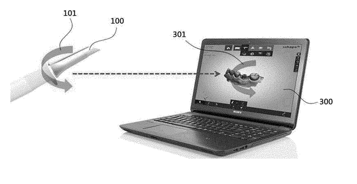
The present invention proposes an intraoral scanner system that reduces scan time by correcting errors in real-time imaging. The system allows for mode switching and image processing of a three-dimensional modeling image, making overall operations simple and convenient. Additionally, there is no cross contact between the intraoral scanner and a device such as a PC, preventing secondary infection.

Problems solved by technology

However, the impression taking is problematic due to material consumption and cross infections.
In addition, there is a possibility of breakage and inadequate preservation of the manufactured impression or gypsum model.
However, since the two-dimensional projection image shows a three-dimensional structure in a two-dimensional plane, errors such as distortion or unstitching may occur.
In addition, since radiation is applied to the patient, it may cause medical problems and financially burden the patient.
Furthermore, use of the above method is complicated.
In addition, the user has to directly manipulate the PC to re-image when the three-dimensional modeling images of the first, second, and third scan modes are abnormal.
Therefore, the overall operation time increases and there is also a problem that secondary infection may occur due to cross-contact between the intraoral scanner and a device such as PC, since the user manipulates the PC with his or her hand and operates the intraoral scanner again with that hand.

Method used


Image

  • Dental intraoral scanner system
  • Dental intraoral scanner system
  • Dental intraoral scanner system

Examples


Embodiment Construction

[0031]Embodiments of the present disclosure will now be described in detail with reference to the accompanying drawings. The disclosure may, however, be exemplified in many different forms and should not be construed as being limited to the specific embodiments set forth herein. In the drawings, the shapes and sizes of elements may be exaggerated for the sake of clearer description. Reference now should be made to the drawings, in which the same reference numerals are used throughout the different drawings to designate the same or similar components.

[0032]Through the whole document, the term “connected to” or “coupled to” that is used to designate a connection or coupling of one element to another element includes both a case that an element is “directly connected or coupled to” another element and a case that an element is “electronically connected or coupled to” another element via still another element. Also, when a part may “include or comprise” a certain constituent element, un...


PUM


Abstract

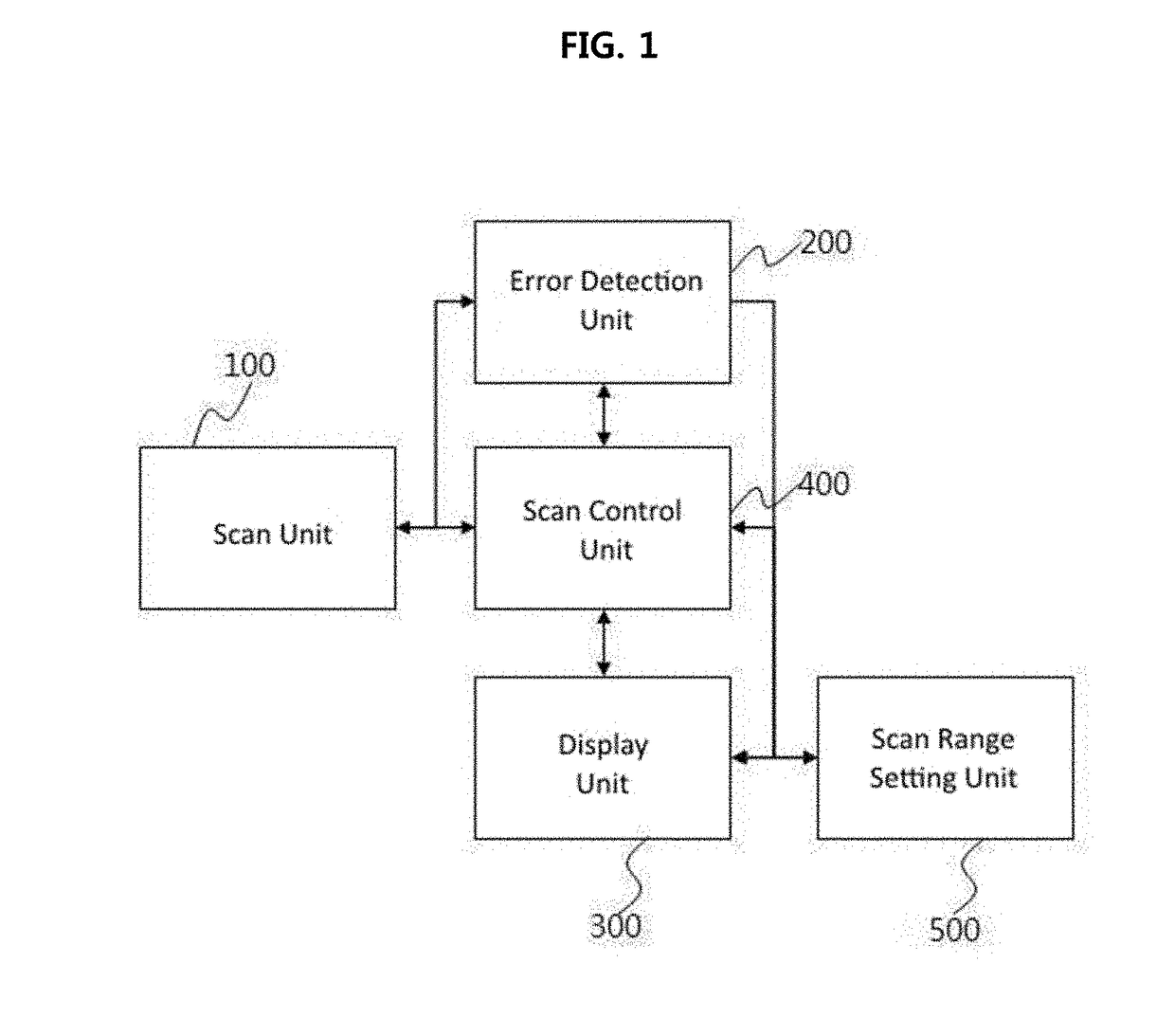
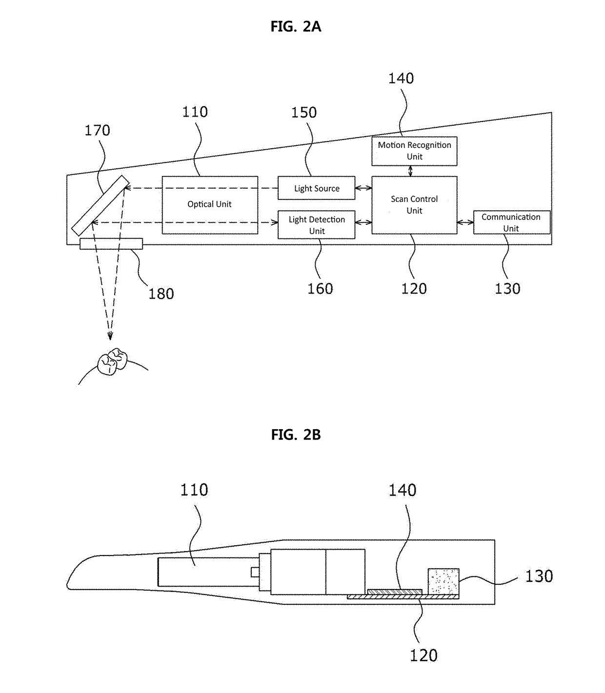
The present invention generally relates to a dental intraoral scanner system. In detail, the present invention includes: a scan unit sequentially imaging an intraoral structure in a scan mode; a control unit generating a three-dimensional modeling image for each scan mode by using the imaged intraoral structure; and a display unit displaying the three-dimensional modeling image, wherein the control unit switches the scan unit from a present scan mode to a following scan mode according to a user's command that is input through the scanning unit, or automatically switches from the present scan mode to the following scan mode when a three-dimensional modeling image of the present scan mode is completed.

Description

CROSS REFERENCE TO RELATED APPLICATION[0001]The present application claims priority to Korean Patent Application No. 10-2016-0038041, filed Mar. 30, 2016, the entire contents of which is incorporated herein for all purposes by this reference.BACKGROUND ARTTechnical Field[0002]The present invention generally relates to a dental intraoral scanner system. More particularly, the present invention relates to a dental intraoral scanner system capable of being switched to a scan mode for imaging an intraoral structure and of image processing by using an intraoral scanner.Description of the Related Art[0003]Generally, in dental hospitals, structures of oral tissues such as the teeth of a patient are identified by performing impression-taking of teeth, and based on this, medical treatment is performed. However, the impression taking is problematic due to material consumption and cross infections. In addition, there is a possibility of breakage and inadequate preservation of the manufactured ...

Claims


Application Information

Patent Timeline
IPC IPC(8): H04N13/02A61B1/045A61B1/24A61C9/00G06T17/00A61B1/00
CPCH04N13/0207H04N13/0296G06T17/00A61B1/00006A61B1/00045H04N5/2256A61C9/0053A61B1/00055A61B1/00039A61B1/045H04N2005/2255A61B1/24G06T19/20G06T2219/2016A61B1/00016A61B1/0005A61B1/247A61B5/1077A61B5/1079A61B5/7221A61B5/4547A61B2562/0219A61B1/0004A61B1/00194H04N23/555H04N23/60A61B5/0062A61B5/0088H04N23/56H04N13/207H04N13/296
Inventor LEE, JUNGCHUN, JIN PYOJO, HYEONG JIN
Owner VA TECHNOLOGIE
Learn More