
Insertion device

a technology of insertion device and insertion device, which is applied in the field of medical devices, can solve the problems of not producing or properly using insulin, the current process requires many complex steps, and the use model of this type of durable insertion device is generally complex

Active Publication Date: 2017-10-12
MEDTRONIC MIMIMED INC
View PDF0 Cites 62 Cited by
  • Summary
  • Abstract
  • Description
  • Claims
  • Application Information

AI Technical Summary

Benefits of technology

The patent describes a sensor assembly that helps to hold a sensor in place and enter a patient's body. It also includes a funnel that creates a tight seal between the cannula and the connection portion. Other features include a lid that protects the contents of the insertion device and a lock collar that securely holds the assembly in place. Overall, this invention provides better protection and reliability for the sensor and insertion process.

Problems solved by technology

Diabetes is a disease in which the body does not produce or properly use insulin.
This type of durable insertion device presents various issues.
For example, the use model for this type of durable insertion device is generally complex, that is, the current process requires many complex steps, some of which may require fine motor skills for the user.
Current durable insertion devices are also prone to wear and damage.
If the user is not carrying the insertion device, the user cannot insert the sensor.

Method used


Image

  • Insertion device
  • Insertion device
  • Insertion device

Examples


embodiment 1

Alternative Rigid Flex Connector

[0468]Referring to FIGS. 69A-69B, exploded views of a sensor module having a back to back sensor connection with a rigid flex connector are illustrated according to alternative embodiments of the present disclosure. FIG. 69A is an exploded top view of the sensor module having a back to back sensor connection with a rigid flex connector according to an alternative embodiment of the present disclosure, and FIG. 69B is an exploded bottom view of the sensor module of FIG. 69A according to an alternative embodiment of the present disclosure.

[0469]As illustrated in FIG. 69A and FIG. 69B, a sensor module 6901 includes a first sensor, e.g., an upper sensor 6940, a second sensor, e.g., a lower sensor 6944 and a flex circuit 6948. As illustrated in FIG. 69A, upper sensor 6940 includes a sensor head having at least one upper sensor contact pad 6935. In this embodiment, three upper sensor contact pads 6935 are illustrated. Also, three windows 6959 on the sensor h...

embodiment 2

Alternative Flex Connector Integrated with Lower Sensor

[0488]FIG. 76 illustrates a perspective view of a lower sensor with conducting pads and an integrated flex connector according to an embodiment of the present disclosure. A first sensor, e.g., a lower sensor 7644 is similar to lower sensor 6944 described above with respect to the embodiment of FIG. 69A-69B, except that conducting pads 7654 are integrated into a portion of an area such as on a side of lower sensor 6944 that extends from the lower sensor head. As such, lower sensor 7644 includes at least one lower sensor contact pad 7639. In this embodiment, three lower sensor contact pads 7639 are illustrated. Lower sensor 7644 also includes a leg 7638 extending from the lower sensor head. In one or more embodiments, at least one electrode 7638a, for example three electrodes 7638a as illustrated in this embodiment of FIG. 76, are placed on the extension or leg 7638. In various embodiments, lower sensor 7644 is foldable or otherwi...

embodiment 3

Alternative Flex Connector Integrated with Sensor, Sensors Interlaced

[0493]FIGS. 79A-79B illustrate exploded views of a sensor module having conducting pads integrated into a sensor according to an alternative embodiment of the present disclosure. FIG. 79A is a top exploded view of the sensor module having conducting pads integrated into a sensor according to an alternative embodiment of the present disclosure. FIG. 79B is a bottom exploded view of the sensor module of FIG. 79A according to an alternative embodiment of the present disclosure.

[0494]As illustrated in FIG. 79A and FIG. 79B, a sensor module includes a first sensor 7940 and a second sensor 7944. As illustrated in FIG. 79A, first sensor 7940 includes a sensor head having at least one sensor contact pad 7935 and at least one conducting pad 7954 integrated on the first sensor itself, for example on a portion of the first sensor head such as a portion extending from the first sensor head. In this embodiment, three sensor con...


PUM


Abstract

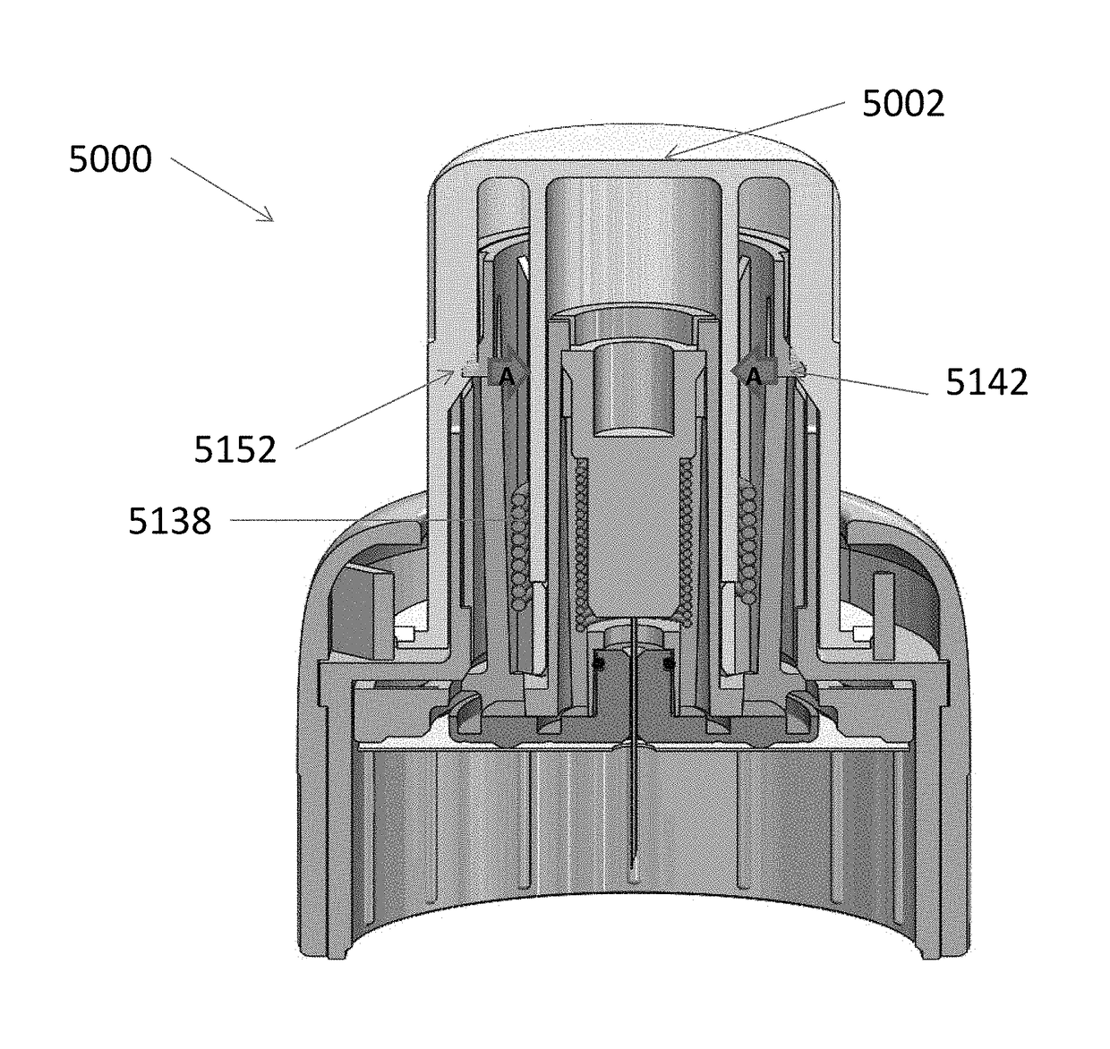
Embodiments relate to an insertion device that includes: a plunger coupled with a lock collar. The insertion device houses contents including: a striker including self-locking striker snap arm(s) where the striker is kept from firing by a striker spring captured between the plunger and the striker when the insertion device is in a cocked position; a sensor assembly; and a needle carrier that holds a piercing member, the needle carrier captured between the striker and a needle carrier spring where a self-releasing snap(s) keeps the needle carrier cocked, where the plunger prevents the self-releasing snap(s) from repositioning and releasing the needle carrier. The striker fires the needle carrier such that the self-locking striker snap arm(s) are positioned to allow the striker to snap down. The needle carrier is then retracted when the user releases the plunger and the piercing member is encapsulated within the insertion device.

Description

RELATED APPLICATIONS[0001]The present disclosure claims priority to and the benefit of U.S. Provisional Patent Application Ser. No. 62 / 320,290 filed on Apr. 8, 2016, U.S. Provisional Application Ser. No. 62 / 344,847 filed on Jun. 2, 2016, U.S. Provisional Patent Application Ser. No. 62 / 344,852 filed on Jun. 2, 2016, and U.S. Provisional Patent Application Ser. No. 62 / 402,676 filed on Sep. 30, 2016, the contents of which are incorporated herein by reference in their entirety.TECHNICAL FIELD[0002]Embodiments of the present disclosure generally relate to medical devices, and more particularly, to medical devices or products having a sensor and a transmitter and their associated components, connections and arrangement techniques.BACKGROUND[0003]Diabetes is a disease in which the body does not produce or properly use insulin. Millions of people in the United States and around the world have been diagnosed with some form of diabetes. Type 1 diabetes results from the body's failure to produ...

Claims


Application Information

Patent Timeline
Patent Type & Authority Applications(United States)
IPC IPC(8): A61B5/145
CPCA61B5/14503A61B5/14532A61B5/150022A61B5/150969A61M5/1723A61B2560/0214A61M2005/1586A61M2005/1585A61M2205/3569A61B5/14865A61B5/6833A61B2560/045A61B2562/227A61M5/158A61B5/1473A61B5/0022A61B5/1486A61B5/150236A61B5/150633A61B5/150732A61B5/6832A61B2562/04A61B2562/16A61M2005/1726A61B5/145A61B2560/063A61B5/0002
Inventor ANTONIO, DAVID C.LARSON, ERIC ALLANRUELAS, JOSE J.
Owner MEDTRONIC MIMIMED INC
Learn More