Servo control apparatus for driving plurality of motors
a technology of servo control and plurality of motors, which is applied in the direction of electric programme control, program control, instruments, etc., can solve the problems of losing the appropriate control of the driven object, and achieve the effect of maintaining the controllability in relational relationship
- Summary
- Abstract
- Description
- Claims
- Application Information
AI Technical Summary
Benefits of technology
Problems solved by technology
Method used
Image

Examples
first embodiment
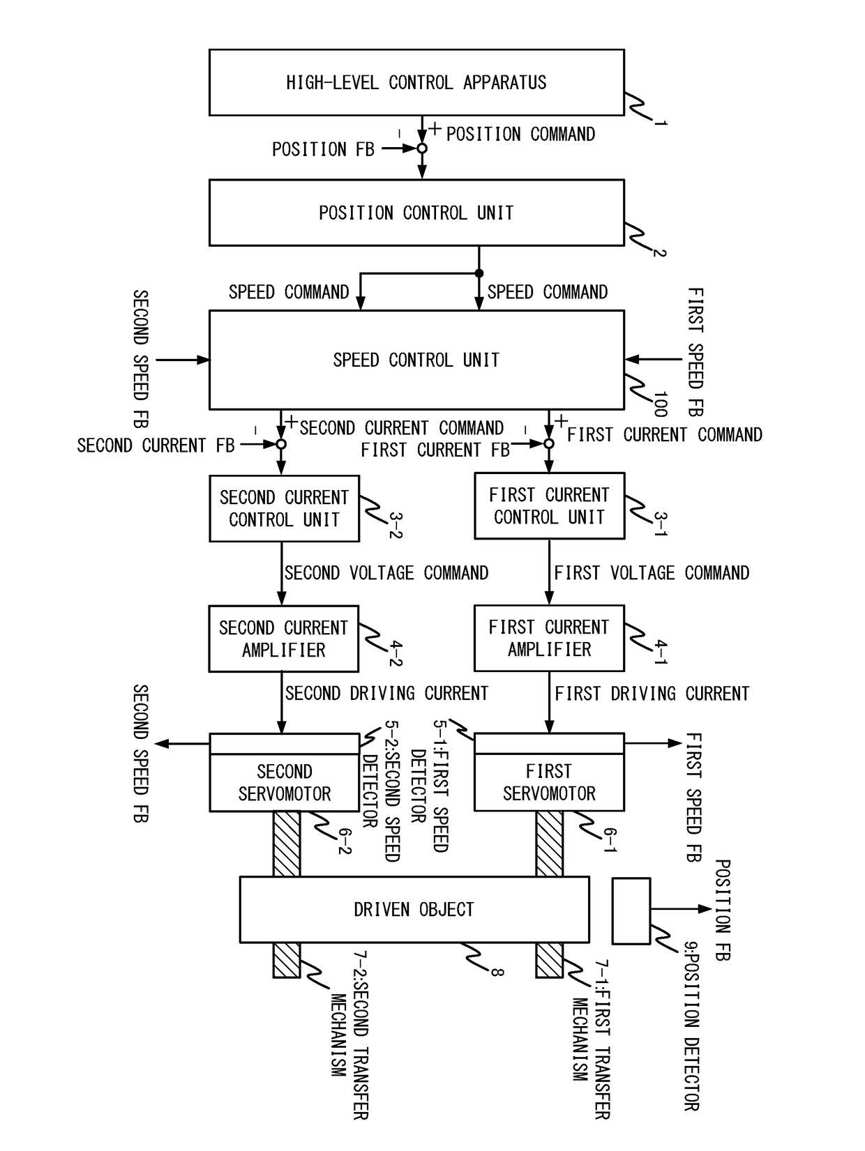
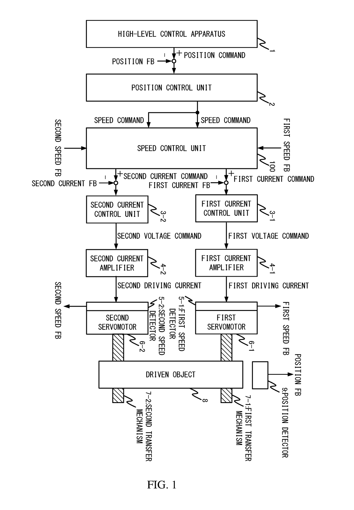
[0027]At first, the first embodiment is described. As illustrated in FIG. 1, the present embodiment includes a high-level control apparatus 1, a position control unit 2, a speed control unit 100, a first current control unit 3-1, a first current amplifier 4-1, a first speed detector 5-1, a first servomotor 6-1, a first transfer mechanism 7-1, a second current control unit 3-2, a second current amplifier 4-2, a second speed detector 5-2, a second servomotor 6-2, a second transfer mechanism 7-2, a driven object 8, and a position detector 9.
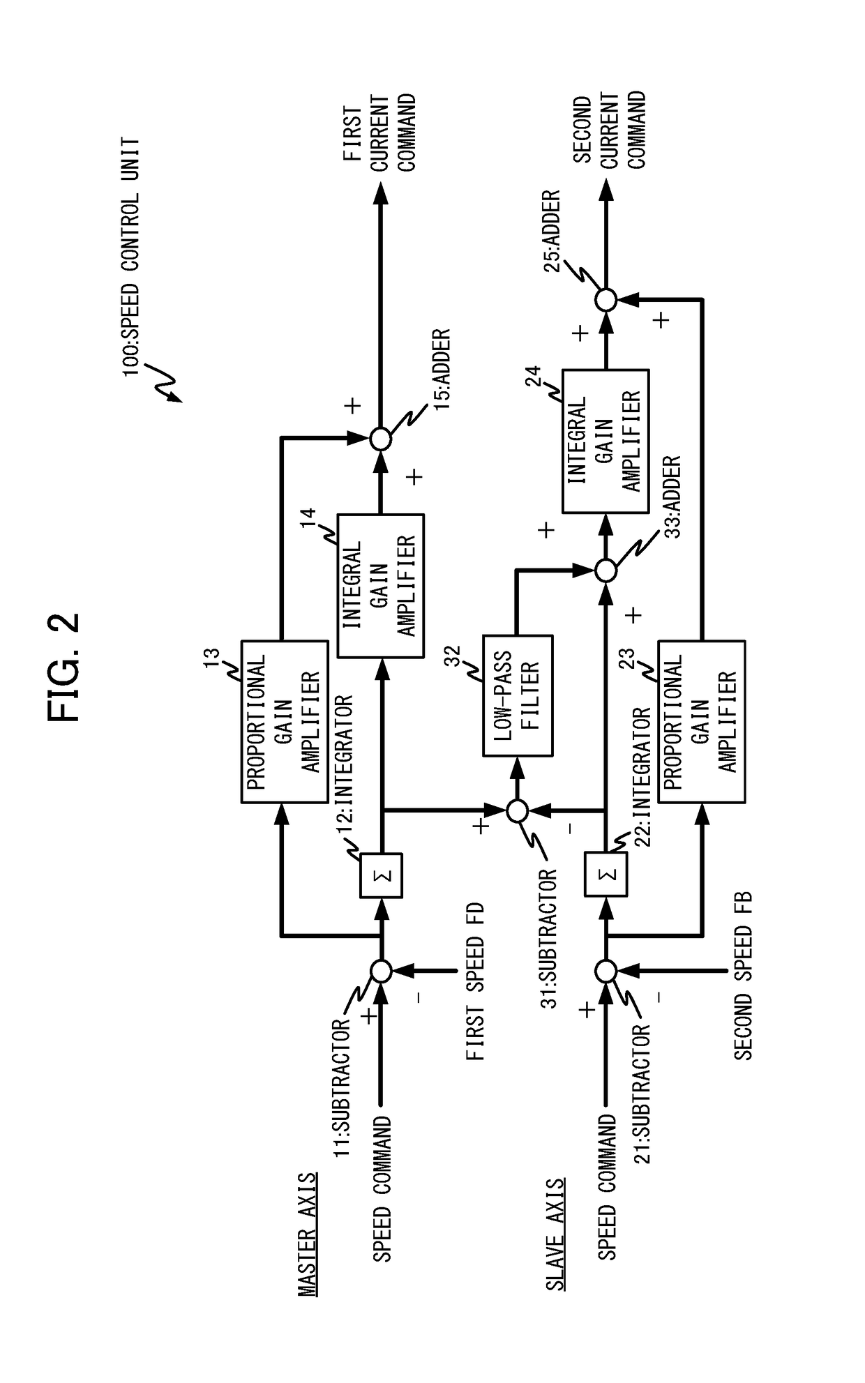
[0028]The present embodiment performs tandem control of a drive mechanism for driving one driven object 8 by way of two servomotors including a first servomotor 6-1 and a second servomotor 6-2. Further, in accordance with this, the speed control unit 100 performs processing that is characteristic of the present embodiment, thereby correcting an integral value of a speed integrator of the slave axis, while maintaining the controllability of the drive...
second embodiment
[0058]Next, a second embodiment altered from the first embodiment is described with reference to the drawings. Here, in the first embodiment, one driven object is driven by way of one master axis and one slave axis. On the other hand, the second embodiment is different in that the slave axis is increased to N axes (N is a natural number of 2 or more), and one driven object is driven by way of one master axis and N slave axes. Note that the first embodiment and the second embodiment share the other basic configuration and processing. Thus, only the difference from the first embodiment is described below; and descriptions on the shared features, which overlap with the first embodiment, are omitted herein.
[0059]Referring now to FIG. 5, the present embodiment includes the first current control unit 3-1, the first current amplifier 4-1, the first speed detector 5-1, the first servomotor 6-1, and the first transfer mechanism 7-1, all of which correspond to the master axis; and further inc...
third embodiment
[0062]Next, a third embodiment is described with reference to the drawings. Note that, although the third embodiment altered from the first embodiment is described below, the third embodiment may be altered from the second embodiment including the N slave axes. Here, the present embodiment additionally includes a function to estimate mechanical coupling rigidity between the slave axis and the master axis, via the first transfer mechanism 7-1, the second transfer mechanism 7-2, and the driven object 8; and adjusts the cutoff frequency determined by the time constant of the low-pass filter, based on the estimated result. Note that the present embodiment shares the other basic configuration and processing with the first and second embodiments. Thus, only the difference from the first and second embodiments is described below; and descriptions on the shared features, which overlap with the first and second embodiments, are omitted herein.
[0063]Referring now to FIG. 7, in the present emb...
PUM
 Abstract
Description
Claims
Application Information
 - R&D
- Intellectual Property
- Life Sciences
- Materials
- Tech Scout
- Unparalleled Data Quality
- Higher Quality Content
- 60% Fewer Hallucinations
Browse by: Latest US Patents, China's latest patents, Technical Efficacy Thesaurus, Application Domain, Technology Topic, Popular Technical Reports.
© 2025 PatSnap. All rights reserved.Legal|Privacy policy|Modern Slavery Act Transparency Statement|Sitemap|About US| Contact US: help@patsnap.com