Fingerprint authorisable device

a fingerprint authorization and fingerprint technology, applied in the field of fingerprint authorization devices, can solve the problems of inability to recognize fingerprints/palmprints, surface damage, sensor wear and tear, etc., and achieve the effect of less accuracy and good ohmic conta

Inactive Publication Date: 2017-10-12
ZWIPE
View PDF2 Cites 10 Cited by
  • Summary
  • Abstract
  • Description
  • Claims
  • Application Information

AI Technical Summary

Benefits of technology

[0064]Preferably, the transition member is connected to the contacts using a conductive adhesive (e.g. a conductive epoxy). This ensures a good ohmic contact between the sensor and the contacts within the cavity.
[0065]The conductive adhesive may be an anisotropic conductive adhesive. As above, the

Problems solved by technology

However, the current inventor has made the realization that this surface is still susceptible to damage, especially in the case where the fingerprint authorizable device may be used frequently, such as in the example of a smartcard that could be used many times each day.
No matter where a fingerprint sensor is deployed, the sensor will undergo wear and tear as users place their fingers on the device for identification of an authorized fingerprint.
As a consequence, fingerprint sensors can have shortened life spans due to the fact that a user must make physical contact in order for the device to successfully capture a fingerprint to provide identification verification.
In many situations users of the fingerprin

Method used


Image

  • Fingerprint authorisable device
  • Fingerprint authorisable device
  • Fingerprint authorisable device

Examples


Embodiment Construction

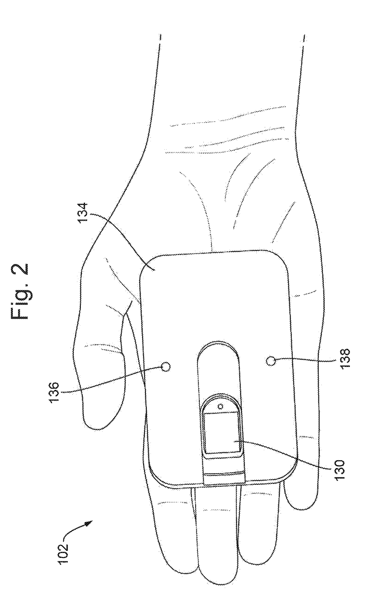
[0079]By way of example the invention is described in the context of a fingerprint authorized smartcard that includes contactless technology and uses power harvested from the card reader. These features are envisaged to be advantageous features of one application of the proposed fingerprint sensor assembly, but are not seen as essential features. The smartcard may hence alternatively use a physical contact and / or include a battery providing internal power, for example. The fingerprint sensor assembly 130 described herein can also be implemented with appropriate modifications in any other device or system that uses a fingerprint sensor for fingerprint authorization.

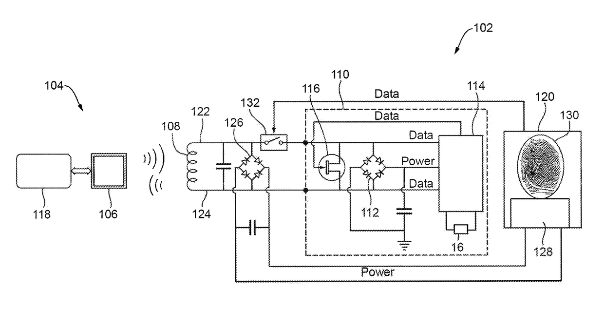
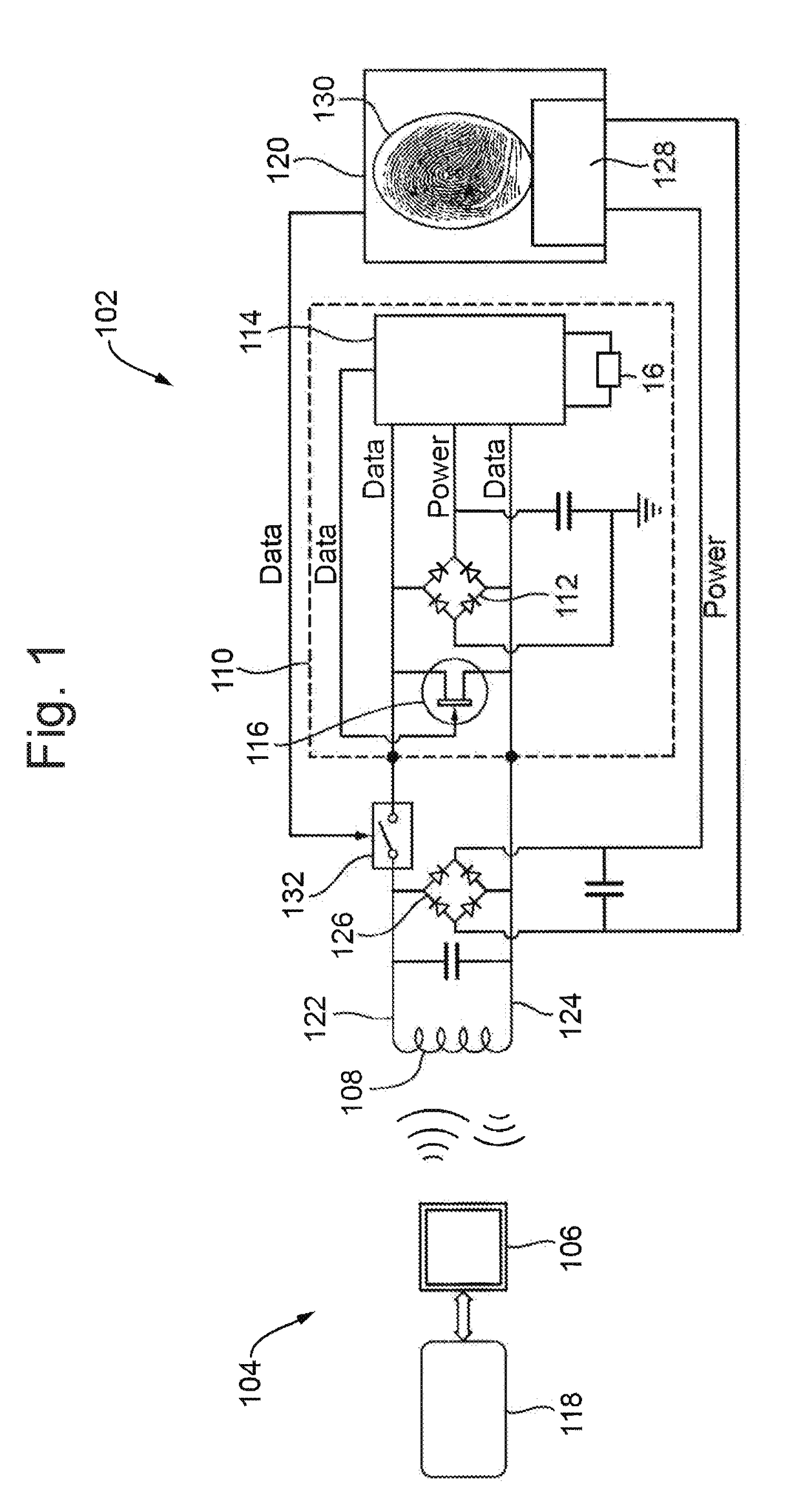
[0080]FIG. 1 shows the architecture of a smartcard 102 that is provided with the fingerprint sensor assembly 130. A powered card reader 104 transmits a signal via an antenna 106. The signal is typically 13.56 MHz for MIFARE® and DESFire® systems, manufactured by NXP Semiconductors, but may be 125 kHz for lower frequency PR...


PUM


Abstract

A fingerprint authorizable device includes a control system for controlling the device, where the control system is arranged to provide access to one or more functions of the device in response to identification of an authorized fingerprint, a circuit board for holding electrical components of the device, and a fingerprint sensor assembly including a fingerprint sensor for obtaining fingerprint data for use in the fingerprint authorization, and a two part enclosure for holding the fingerprint sensor, the two part enclosure having an inner casing for attachment to the circuit board and for enclosing the fingerprint sensor and an outer bezel for retaining the fingerprint sensor within the inner casing, where the outer bezel is arranged to be coupled to the inner casing.

Description

CROSS REFERENCE TO RELATED APPLICATION[0001]This application is related to and claims the benefit of U.S. Provisional patent application No. 62 / 320,716 filed on 11 Apr. 2016 and Great Britain Patent Application Number 1608189.5 filed on 10 May 2016, the contents of both of said applications being herein incorporated by reference in their entirety.TECHNICAL FIELD[0002]The present invention relates to a fingerprint authorizable device and to a method for manufacturing a fingerprint authorizable device.BACKGROUND[0003]Fingerprint authorized devices such as smartcards are becoming increasingly more widely used. Smartcards for which biometric authorization has been proposed include, for example, access cards, credit cards, debit cards, pre-pay cards, loyalty cards, identity cards, cryptographic cards, and so on. Smartcards are electronic cards with the ability to store data and to interact with the user and / or with outside devices, for example via contactless technologies such as RFID. T...

Claims


Application Information

Patent Timeline
IPC IPC(8): G06K9/00G07C9/00G06F21/31
CPCG06K9/00053G06K9/00087G06K9/0002G07C9/00111G06F21/31G06F21/32G07C9/26G07C9/257G06V40/1329G06V40/28G06V40/70G07C9/28G06V40/1365G06V40/1306
Inventor LAVIN, JOSE IGNACIO WINTERGERST
Owner ZWIPE
Why Eureka
Try Eureka