Thin-film solar cell and manufacture method therefor

a technology of thin film and solar cells, applied in the direction of electrolysis components, vacuum evaporation coatings, coatings, etc., can solve the problems of production costs, complex apparatus, and metal itself diffraction

Inactive Publication Date: 2003-09-11
SHARP KK
View PDF2 Cites 25 Cited by
  • Summary
  • Abstract
  • Description
  • Claims
  • Application Information

AI Technical Summary

Problems solved by technology

One of the most important challenges for putting solar cells into practical use is to reduce production costs.
However, if a film of a reflective metal is used as a rear electrode, the metal itself diffuses into the semiconductor layer to deteriorate characteristics of the solar cell or to establish conduction with an electrode on the light-incident side and cause a shunt.
However, if (1) a magnetron sputtering apparatus of the magnet-fixed substrate-fixed type is used for forming a thin film on a fixed substrate with a large area, a large number of magnets are required to be mounted to cover a large film-formation region.
Thus the apparatus becomes complicated and the production costs rise.
Even if magnets are used in a great number, it is difficult to form a uniform magnetic field over the large film-formation region owing to non-uniform consumption of a target and other causes.
Thus the film formed by deposition is still non-uniform.
Yet neither the apparatus (1) nor (2) provides a sufficient fill factor as an output characteristic of solar cells owing to unsatisfactory quality of the obtained film as the rear transparent electrode layer and unsatisfactory junction state between the photovoltaic conversion layer and the transparent electrode layer.
However, a single film of Ga-doped ZnO does not contribute to reduction in the production costs.
The change of a target with time prevents obtainment of stable film quality and declines the fill factor.
In the case where a magnet sputtering apparatus is used for forming the rear transparent electrode layer, a film formed at an initial stage of discharge cannot have a good ohmic contact with the photovoltaic conversion layer and a sufficient fill factor cannot be obtained, owing to a trace of residual oxygen adsorbed on the surface of a target and / or powdery contaminants containing metal and adhering to the surface of the target.
In addition to that, in the case where the rear transparent electrode layer is formed when the vacuum degree is poor before its formation, the contact with the photovoltaic conversion layer tends to worsen remarkably.
However, according to the present invention, the ITO target and the ZnO:Al target are placed in the same chamber, and thus the control of the amount of oxygen is particularly difficult, so that oxygen may have adverse effect as contamination.

Method used


Image

  • Thin-film solar cell and manufacture method therefor
  • Thin-film solar cell and manufacture method therefor

Examples


Embodiment Construction

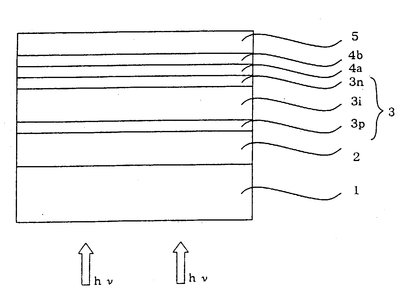
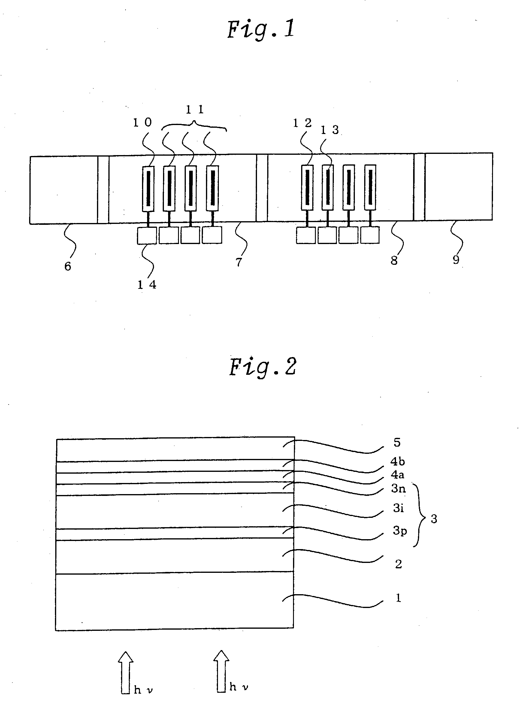
, the substrate 1 was heated to 150.degree. C. in the preparation chamber 6, which was vacuumed to 8.times.10.sup.-3 Pa. Before film deposition in the ITO and ZnO deposit chamber 7, the back pressure was set to 3.times.10.sup.-3 Pa. In the ITO and ZnO deposit chamber 7, used was an ITO target produced by cold pressing which had a relative density of 92% and a tin content of 5 wt % or an ZnO:Ga target produced by cold pressing which had a relative density of 92% and a Ga content of 5 wt %. In a state of a cumulative discharge power energy of 100 kWh, ITO or ZnO:Ga and ZnO:Al were deposited to 25 nm and 75 nm thickness, respectively. The magnetic field intensity was 1,000 G on the surfaces of all the targets, and the discharge power was DC 2.5 W / cm.sup.2 for all the targets.

[0047] As Production Example 2, the glass substrate 1 was heated in the preparation chamber 6, which was vacuumed, in the same manner as in Production Example 1. In the ITO and ZnO deposit chamber 7, used was an IT...


PUM

PropertyMeasurementUnit
thickaaaaaaaaaa
thickaaaaaaaaaa
magnetic field intensityaaaaaaaaaa

Abstract

A thin-film solar cell including a transparent electrode layer, a semiconductor photovoltaic conversion layer, a rear transparent electrode layer and a rear reflective metal layer, said layers being formed in this order on a transparent substrate, wherein the rear transparent electrode has a two-layer structure of an ITO or ZnO:Ga layer and a ZnO:Al layer formed in this order on the semiconductor photovoltaic conversion layer.

Description

CROSS-REFERENCES TO RELATED APPLICATIONS[0001] This application is related to Japanese Patent Applications Nos. 2002-65585 filed on Mar. 11, 2002 and No. 2003-2160, filed on Jan. 8, 2003 whose priorities are claimed under 35 USC .sctn.119, the disclosures of which are incorporated by reference in their entirety.[0002] 1. Field of the Invention[0003] The present invention relates to a thin-film solar cell and a manufacture method therefor, more particularly to a thin-film solar cell having a transparent electrode layer that allows improvement of performance of the thin-film solar cell including, for example, photovoltaic conversion efficiency, and a manufacture method therefor.[0004] 2. Description of Related Art[0005] Solar cells are photovoltaic conversion devices which convert solar light into electric energy and are expected to provide clean energy alternative to nuclear energy and fossil energy such as petroleum. One of the most important challenges for putting solar cells into ...

Claims


Application Information

Patent Timeline
Patent Type & Authority Applications(United States)
IPC IPC(8): C23C14/08H01L31/00H01L31/0224H01L31/04H01L31/18
CPCC23C14/086Y02E10/50H01L31/1884H01L31/022466H01L31/022475H01L31/022483
Inventor OUCHIDA, TAKASHISANNOMIYA, HITOSHI
Owner SHARP KK
Why Eureka
Try Eureka