Water treatment system and method

a technology for water treatment and water treatment, applied in the field of water treatment, can solve the problems of low innovation in design and operation, system existence for decades, and difficult treatment effectively, and achieve the effects of reducing discharge costs, reducing discharge costs, and reducing quality

Active Publication Date: 2017-10-19
WATERWERX TECH PTY LTD
View PDF0 Cites 22 Cited by
  • Summary
  • Abstract
  • Description
  • Claims
  • Application Information

AI Technical Summary

Benefits of technology

[0044]By allowing the user to determine a desired water quality result, the present invention considers not only the cost of input chemicals to be controlled, but also the cost of discharge of the treated water. Higher quality water generally attracts lower discharge costs, given that these costs are generally proportional to the amount of contaminants contained therein (although other factors may

Problems solved by technology

The dynamic and composite nature of industrial effluent makes it extremely difficult to treat effectively.
These systems have been around for decades with little innovation in relation to their design and operation.
Due to the diverse composition of industrial effluent and the complex interactions between these components, the optimum chemical dosage to treat a particular effluent stream through a DAF system is impossible to predict theoretically.
This complexity is compounded by the fact that the flow rate and composition of the effluent stream changes continuously over time.
The cost of treating discharged water is based on the contaminants present in the waste water; the higher the contaminant loading, the more expensive it is to treat the discharged water.
Although the water quality can be increased by, for example, increasing the volume of certain chemicals added to the water treatment process, the additional chemical cost leads to an increase in the overall cost of the treatment pro

Method used


Image

  • Water treatment system and method
  • Water treatment system and method
  • Water treatment system and method

Examples


example 1

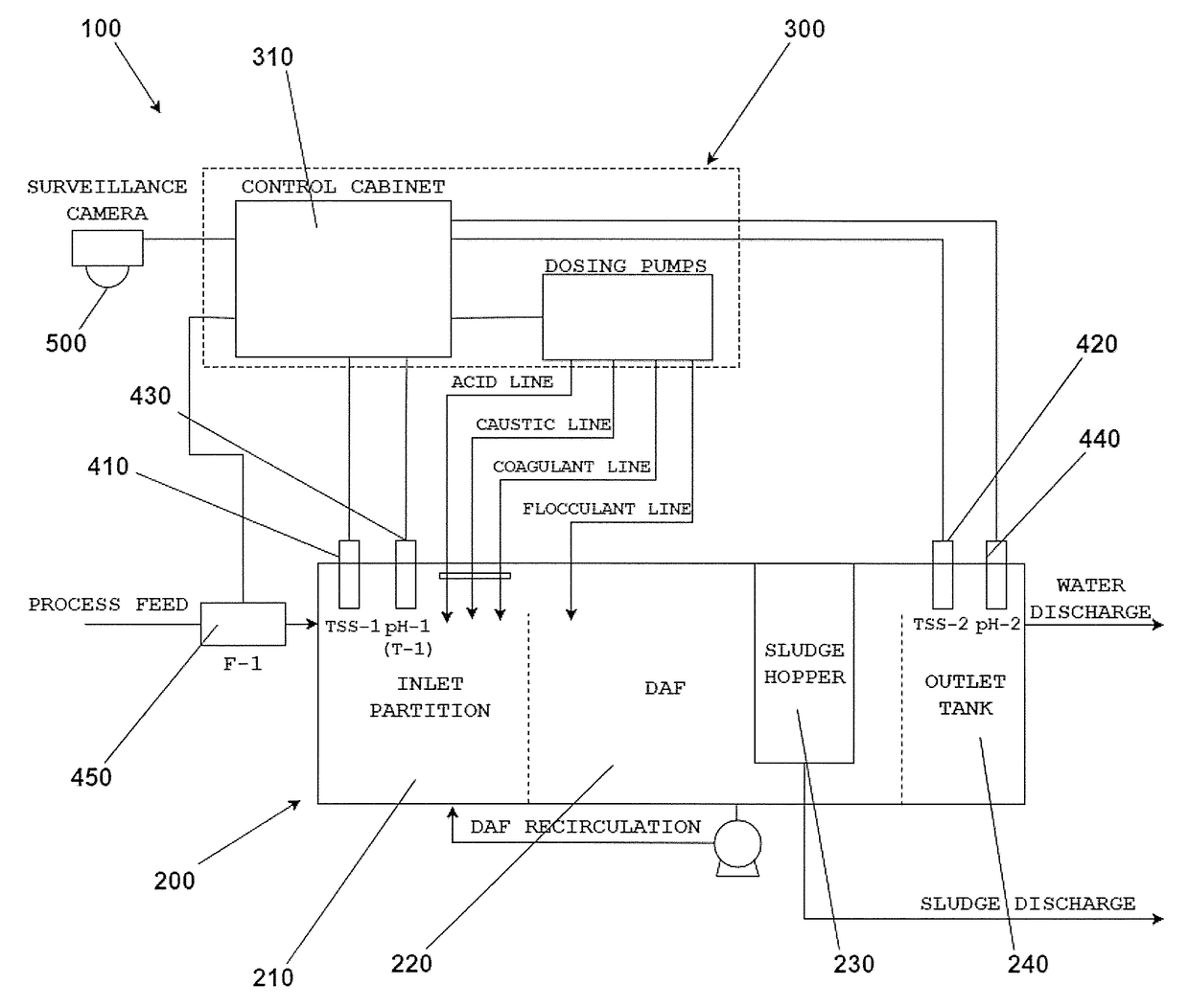
[0231]The present invention was tested on waste water generated at an abattoir. The waste water from the abattoir contained high levels of fats and proteins which contributed to a high level of TSS in the effluent. At the abattoir, this value, measured in parts per million (ppm), fluctuated constantly between 6,000 and 30,000 ppm, with the average value being approximately 10,000 ppm.

[0232]Discharging an effluent stream with a high TSS count can be very costly for a client as part of the discharge cost, as prescribed by the relevant water authorities, is directly proportional to the TSS concentration of the discharged effluent. As a result, the managers of the abattoir opted to treat their waste water to reduce the TSS levels prior to discharging it. Prior to testing the present invention, the managers of the abattoir used a manually operated DAF system to treat the effluent stream, with the chemistry determined by an operator through jar testing.

[0233]Prior to testing the present i...


PUM


Abstract

Disclosed herein is a water treatment system for connection to a water treatment plant (e.g. a dissolved air flotation device). The plant may have an inlet for the receipt of feed water (e.g. waste water) and an outlet for the discharge of treated water. The treatment system may comprise a first sensor disposed such that it is in fluidity communication with the feed water, and a second sensor disposed such that it is in fluidity communication with the treated water. The first and second sensors may be configured to sense parameters of the feed and treated water. The system may further comprise a first applicator (e.g. a pump) that is configured to discharge a treatment source (e.g. a chemical source) to the plant to treat the feed water. The disclosed system may be used to treat waste water (e.g. the treatment of effluent from oil refineries, petrochemical and chemical plants, natural gas processing plants, paper mills and general water treatment). The system has analogous applications in other processing methods that also use DAF, or very similar, systems, such as the processing of mineral ores and other such solid extraction processing methods.

Description

TECHNICAL FIELD[0001]The present disclosure relates to the field of water treatment. The present disclosure has particular application to a control and dosing system for a water treatment apparatus.BACKGROUND ART[0002]While the use of dissolved air flotation devices (DAFs) in water treatment is discussed in detail in this specification, the person skilled in the art will be aware that other water treatment apparatus may be used, and such other apparatus are included within the scope of this invention.[0003]Industrial effluent is a complex mixture comprising dissolved organic and inorganic solids, microbes, colloids and other particles, of various sizes, charges and polarities. The dynamic and composite nature of industrial effluent makes it extremely difficult to treat effectively.[0004]Different sources of industrial effluent require markedly different treatment strategies. For example, the meat industry produces effluent containing large amounts of organic materials, whereas minin...

Claims


Application Information

Patent Timeline
IPC IPC(8): C02F1/52C02F1/24C02F103/34
CPCC02F1/5209C02F1/24C02F2103/34C02F2209/10C02F2209/006C02F1/008C02F2209/001C02F2209/003C02F2209/008C02F2209/02C02F2209/06
Inventor WHITAKER, MICHAEL JAMESLOCKEY, ALASTAIRBHARTIA, ABHYUDAYMEIKLE, PETER JOHNRAJENDRAN, SHARMEN
Owner WATERWERX TECH PTY LTD
Why Eureka
Try Eureka