
MRI birdcage coil with distributed excitation

a distributed excitation and coil technology, applied in the direction of magnetic measurement, measurement device, instruments, etc., can solve the problems of large radio frequency current load in the conductive segment for generating, heavy, bulky, etc., and achieve the effect of large differences in radio frequency current load in the conductive segmen

Active Publication Date: 2017-10-19
KONINKLJIJKE PHILIPS NV
View PDF0 Cites 5 Cited by
  • Summary
  • Abstract
  • Description
  • Claims
  • Application Information

AI Technical Summary

Benefits of technology

The invention is a magnetic resonance radio frequency transmission device that has several advantages over existing systems. It uses a tri-coil design with a lower-power hardware module instead of expensive radio frequency components, which reduces costs. It also eliminates the need for circulators and long lossy power cables, making the device more efficient. The device can be operated in different modes, such as quadrature mode excitation or independent dual radio frequency channel (2-mode excitation) multiple transmission mode, for example, for radio frequency shimming. The arrangement of conductive segments in the device is designed to minimize variations in radio frequency current load and achieve a uniform radio frequency excitation field. Finally, the device has a control unit that can adjust the level of radio frequency power and the fixed relationship of adjustable phase angles among the radio frequency amplifier units.

Problems solved by technology

The radio frequency circulators 761, 762 are bulky, heavy and expensive.
The transmission lines have to have an appropriate power rating and thus are heavy, and a trade-off between cost, weight and loss of radio frequency power is required.

Method used


Image

  • MRI birdcage coil with distributed excitation
  • MRI birdcage coil with distributed excitation
  • MRI birdcage coil with distributed excitation

Examples


Embodiment Construction

[0070]In the following, several embodiments in accordance with the invention are disclosed. The individual embodiments are described with reference to a particular figure and are identified by a prefix number of the particular embodiment. Features whose function is the same or basically the same in all embodiments are identified by reference numbers made up of the prefix number of the embodiment to which it relates, followed by the number of the feature. If a feature of an embodiment is not described in the corresponding figure depiction, or a reference number mentioned in a figure depiction is not shown in the figure itself, the description of a preceding embodiment should be referred to.

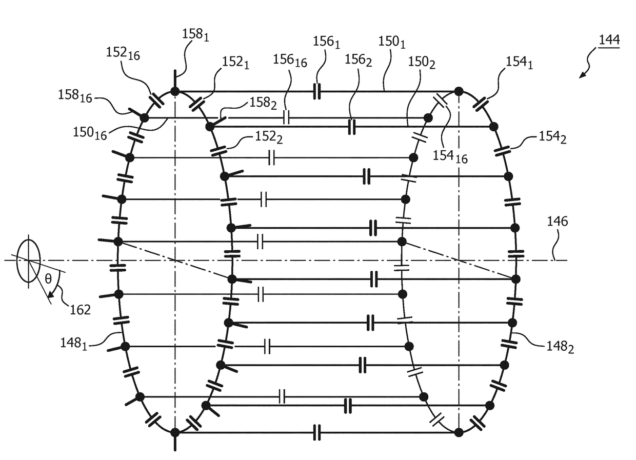
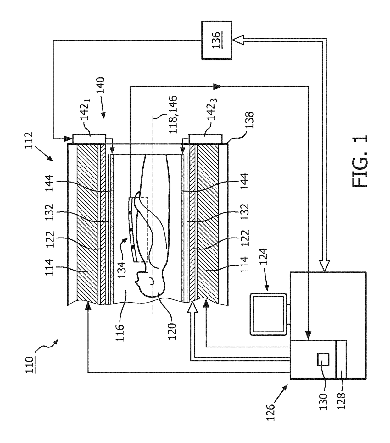
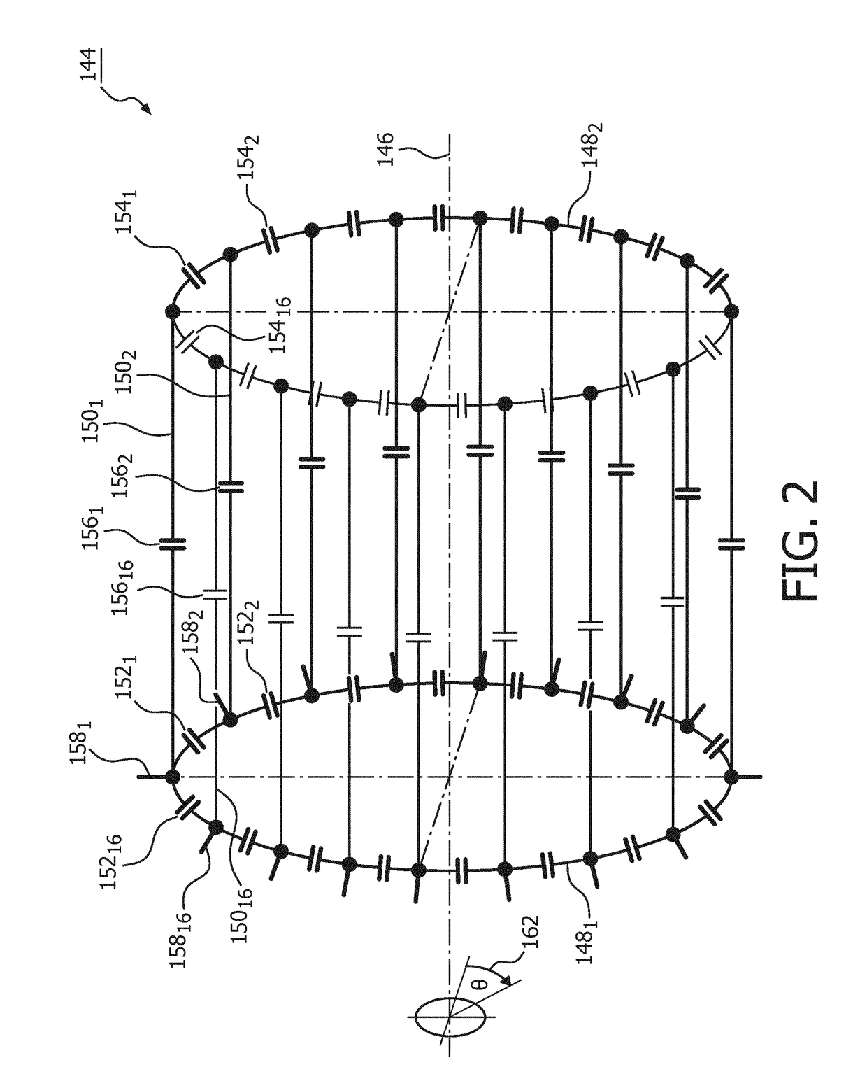
[0071]FIG. 1 shows a schematic illustration of a part of an embodiment of a magnetic resonance imaging system 110 configured for acquiring magnetic resonance images of at least a portion of a subject of interest 120, usually a patient, in accordance with the invention. The magnetic resonance imagin...


PUM


Abstract

A magnetic resonance radio frequency transmission device (140) for generating and applying a radio frequency excitation field B1 for the purpose of magnetic resonance examination comprises a birdcage coil (144) and a plurality of M radio frequency amplifier units for providing radio frequency power at a magnetic resonance frequency to the birdcage coil (144) via a plurality of M activation ports (158) selected out of the plurality of N activation ports (158). In an operational state of the birdcage coil (144) each radio frequency amplifier unit (142) is electrically connected and is arranged in close proximity to an activation port (158). Among the plurality of M radio frequency amplifier units (142), there is established a fixed relationship of adjustable phase angles (φ) of the magnetic resonance radio frequency power provided by the plurality of M radio frequency amplifier units (142); a method of generating and applying a radio frequency excitation field B for the purpose of magnetic resonance examination, using such magnetic resonance radio frequency transmission device (140); and a magnetic resonance imaging system (110) configured for acquiring magnetic resonance images of at least a portion of a subject of interest (120), comprising such magnetic resonance radio frequency transmission device (140).

Description

FIELD OF THE INVENTION[0001]The invention pertains to a magnetic resonance radio frequency transmission device for the purpose of magnetic resonance examination, and a method of generating and applying a radio frequency excitation field B1 for the purpose of magnetic resonance examination, using such magnetic resonance radio frequency transmission device.BACKGROUND OF THE INVENTION[0002]In the art of magnetic resonance examination, the birdcage resonator, also known as birdcage coil, is a well-known volume radio frequency coil design for generating a radio frequency magnetic excitation field B1 to be applied to nuclei of or within a subject of interest for magnetic resonance excitation, wherein the subject of interest is positioned at least partially within the birdcage coil, which in turn is arranged within a static, homogeneous magnetic field B0 arranged substantially perpendicular to the radio frequency magnetic excitation field B1.[0003]In the art, birdcage resonators are known ...

Claims


Application Information

Patent Timeline
Patent Type & Authority Applications(United States)
IPC IPC(8): G01R33/34G01R33/36
CPCG01R33/34076G01R33/3607G01R33/3614G01R33/5659G01R33/3678
Inventor HOLLE, EERKE
Owner KONINKLJIJKE PHILIPS NV
Learn More