Exhaust gas purification catalyst

a technology of exhaust gas and catalyst, which is applied in the direction of physical/chemical process catalysts, separation processes, machines/engines, etc., can solve the problems of excessive pressure loss, achieve high exhaust gas purification performance, reduce the effect of exhaust emissions, and reduce the increase of pressure loss

Active Publication Date: 2017-10-26
CATALER CORP +1
View PDF3 Cites 16 Cited by
  • Summary
  • Abstract
  • Description
  • Claims
  • Application Information

AI Technical Summary

Benefits of technology

[0018]In another preferable embodiment of the exhaust gas purification catalyst disclosed herein, in the thickness direction vertical to the extending direction, with the overall partition wall thickness being Tw, the first catalytic layer is formed to at least 30% of the thickness Tw in the interior of the partition walls. With the catalytic metal being extensively diffused and carried on, it is possible to favorably reduce the increase in pressure loss while producing high exhaust gas purification performance.
[0019]In another preferable embodiment of the exhaust gas purification catalyst disclosed herein, in the extending direction, with the lengths of the first and second catalytic layers being L1 and L2, the first and second catalytic layers are formed with partial overlapping in the extending direction so as to satisfy the next inequality Lw<(L1+L2)<2Lw. The first and second catalytic layers partially overlapping in the extending direction can prevent exhaust gas from “escaping” so as to properly purify (detoxify) the exhaust components. Thus, exhaust emissions can be effectively reduced. Accordingly, higher exhaust gas purification performance can be achieved.

Problems solved by technology

Like this, when the surface of the entrance cells were covered with a catalytic layer, pressure loss may have increased excessively.

Method used


Image

  • Exhaust gas purification catalyst
  • Exhaust gas purification catalyst
  • Exhaust gas purification catalyst

Examples


example 1

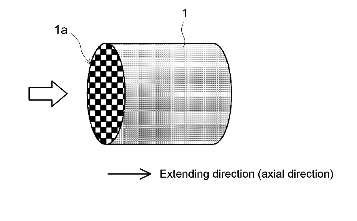
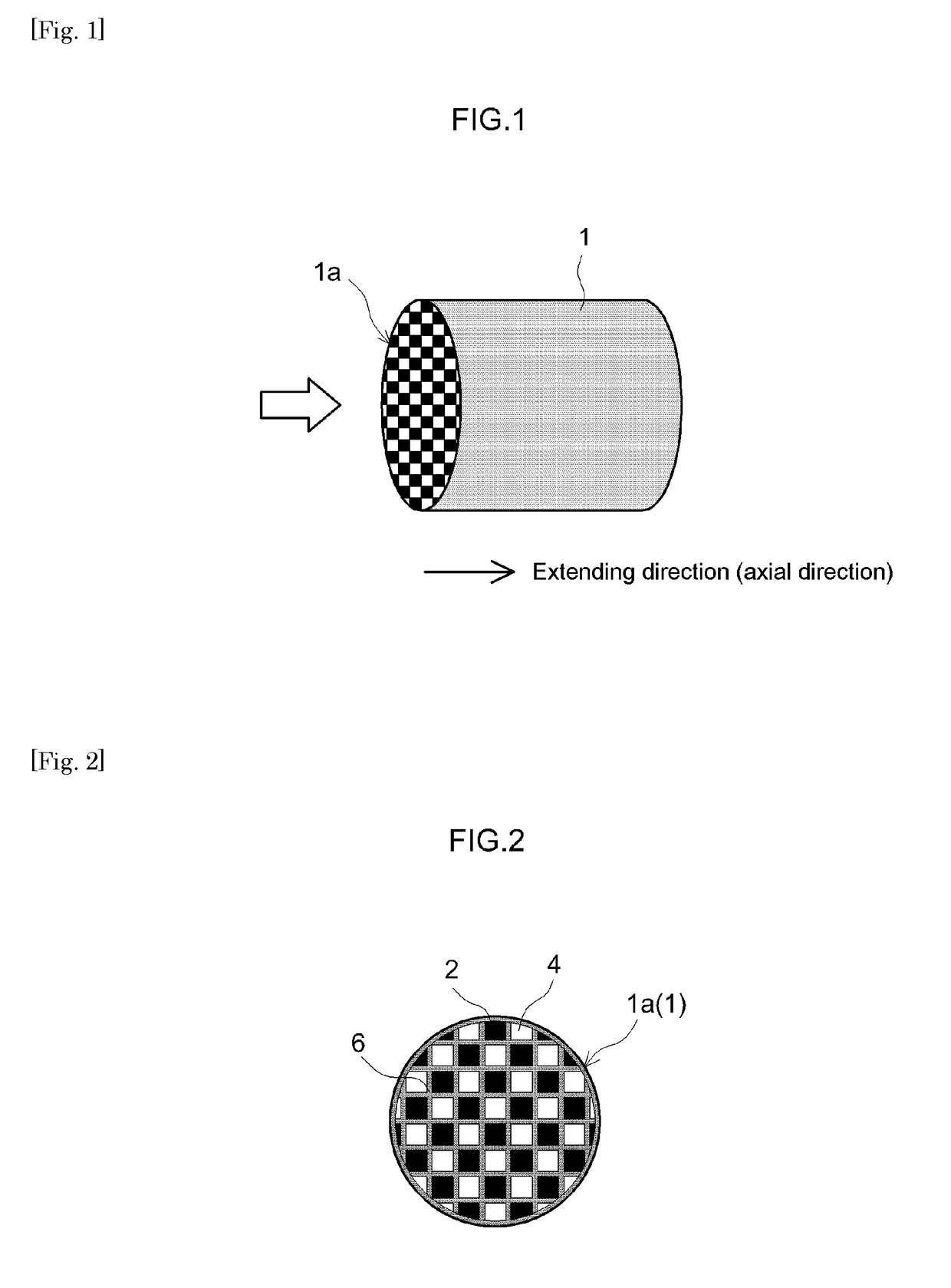
[0059]As the substrate, was obtained a cordierite honeycomb substrate of 300 cpsi (cells per square inch) in the number of cells, 0.9 L in volume (referring to the total bulk volume including the volumes of cell channels), 105 mm in total length, 103 mm in outer diameter, 0.3 mm in partition wall thickness, 15 μm in average pore diameter and 59% in porosity.

[0060]Subsequently, were mixed 40 g of Al2O3 powder (γ-Al2O3, 1 μm average particle diameter) as a support, an aqueous rhodium solution containing 0.5 g Rh, and a suitable amount of pure water. The resulting mixture was mixed with stirring, dried and calcined (500° C., 1 hour) to obtain Rh-carrying powder. With the Rh-carrying powder, were mixed a ceria-zirconia composite oxide solution to yield 60 g of CZ composite oxide upon calcination, and a suitable amount of pure water to prepare the first catalytic layer-forming slurry. The first catalytic layer-forming slurry was supplied from the exhaust inlet-side ends of the honeycomb ...

example 2

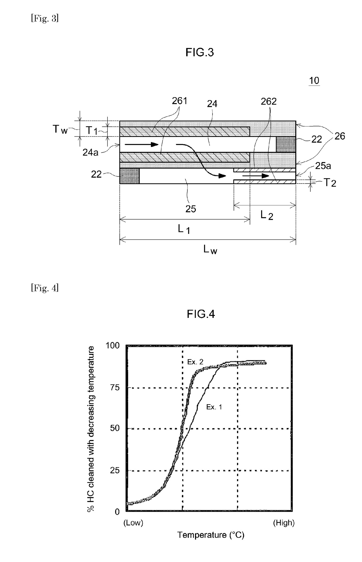
[0063]The second catalytic layer was provided to the surface of the partition walls facing the exit cells. Otherwise in the same manner as Example 1, an exhaust gas purification catalyst (Example 2) was fabricated. In Example 2, because of a difference in features (average particle diameters) of Al2O3 powder as the support, the first catalytic layer was formed in the interior of the partition walls while the second catalytic layer was formed on the surface of the partition walls facing the exit cells. With respect to the second catalytic layer, the length L2 in the extending direction is 55% of the entire partition wall length and the thickness T2 is 20% of the entire partition wall thickness.

[0064]The characteristics of the exhaust gas purification catalysts of the respective Examples are summarized in Table 1 below.

TABLE 1Studies on where catalytic layers are formed1st catalytic layer2nd catalytic layerLength L1Length L2in runningin runningOverlapCatalyticdirectionCatalyticdirecti...

example 3

[0071]The length L1 of the first catalytic layer in its extending direction was 80% of the entire partition wall length and the length L2 of the second catalytic layer in its extending direction was 50% of the entire partition wall length. Otherwise in the same manner as I. Example 2 above, an exhaust gas purification catalyst (Example 3) was fabricated, in which the first catalytic layer was formed in the interior of the partition walls and the second catalytic layer was formed on the surface of the partition walls facing the exit cells.


PUM

PropertyMeasurementUnit
temperatureaaaaaaaaaa
total cell volumeaaaaaaaaaa

Abstract

An exhaust gas purification catalyst having an excellent exhaust gas purification ability while reducing the increase in pressure loss. Exhaust gas purification catalyst includes entrance cell, exit cell, and a wall-flow substrate having partition wall to separate these cell, a catalytic layer formed from exhaust inlet-side ends in the extending direction in sections of the interior of partition wall facing entrance cell, and a catalytic layer formed on the surface of partition wall facing exit cell from exhaust outlet-side ends in the extending direction of partition wall, having a length shorter than the entire partition wall length.

Description

TECHNICAL FIELD[0001]The present invention relates to an exhaust gas purification catalyst provided to an exhaust system of an internal combustion system. In particular, it relates to a wall-flow type exhaust gas purification catalyst.[0002]The present application claims priority to Japanese Patent Application No. 2014-211380 filed on Oct. 16, 2014; the entire contents of which are incorporated herein by reference.BACKGROUND ART[0003]Exhaust gas emitted from an internal combustion system such as an automobile engine comprises toxic components such as particulate matter (PM), hydrocarbons (HC), carbon monoxide (CO), and nitrogen oxides (NOx).[0004]Conventionally, a wall-flow type exhaust gas purification catalyst is used to efficiently eliminate these exhaust components.[0005]A wall-flow exhaust gas purification catalyst comprises entrance cells with open ends on the exhaust inlet side, exit cells with open ends on the exhaust outlet side, and porous partition walls (ribbed walls) to...

Claims


Application Information

Patent Timeline
Patent Type & Authority Applications(United States)
IPC IPC(8): B01D53/94B01J35/04B01J37/02F01N3/28
CPCB01D53/945F01N3/2803B01J37/0244B01J35/04B01D53/9468B01D2255/1021B01D2255/1025B01D2255/2092B01D2255/407B01D2255/9155F01N3/0222F01N2510/0682Y02T10/12
Inventor ONOE, RYOTASAKAGAMI, SHINGOITO, TSUYOSHITAKEUCHI, MASAHIKOMIYOSHI, NAOTOSATO, AKEMI
Owner CATALER CORP
Why Eureka
Try Eureka