
Architecture for a propulsion system of a helicopter including a hybrid turboshaft engine and a system for reactivating said hybrid turboshaft engine

a propulsion system and hybrid technology, applied in the direction of engines/engines, efficient propulsion technologies, engine starters, etc., can solve the problems of high flight points, overconsumption of fuel during cruise flights, and disadvantages of oversized turboshaft engines in terms of weight and fuel consumption

Active Publication Date: 2017-10-26
TURBOMECA SA +1
View PDF6 Cites 18 Cited by
  • Summary
  • Abstract
  • Description
  • Claims
  • Application Information

AI Technical Summary

Benefits of technology

The patent text describes a system that allows a turboshaft engine to quickly reactivate in case of failure. It uses an energy storage unit to provide the necessary power to exit the standby mode of the engine. The system has two separate reactivation systems, so that in case of failure of one system, the other system can take over and ensure a quick recovery of the engine. This system is particularly useful in situations where there is no other alternative for reactivating the engine.

Problems solved by technology

These low levels of power lead to a specific consumption (hereinafter SC), defined as the ratio between the hourly fuel consumption of the combustion chamber of the turboshaft engine and the mechanical power supplied by this turboshaft engine, of approximately 30% greater than the SC of the maximum take-off power, and they therefore lead to an overconsumption of fuel during cruise flight.
This flight situation arises after the loss of an engine and results in the fact that each operating engine supplies a power level much beyond its nominal power so that the helicopter can cope with a dangerous situation, and then continue its flight.
These flight points, which are highly demanding, particularly when the weight of the helicopter is close to its maximum take-off weight, are encountered only in certain circumstances of use.
These oversized turboshaft engines are disadvantageous in terms of weight and fuel consumption.

Method used


Image

  • Architecture for a propulsion system of a helicopter including a hybrid turboshaft engine and a system for reactivating said hybrid turboshaft engine
  • Architecture for a propulsion system of a helicopter including a hybrid turboshaft engine and a system for reactivating said hybrid turboshaft engine
  • Architecture for a propulsion system of a helicopter including a hybrid turboshaft engine and a system for reactivating said hybrid turboshaft engine

Examples


Embodiment Construction

[0058]The embodiments described below are some examples for carrying out the invention. Although the detailed description refers to one or more embodiments, this does not necessarily mean that each reference relates to the same embodiment, or that the features apply only to a single embodiment. Individual features of different embodiments can also be combined in order to provide other embodiments. In addition, in the figures, for the purposes of illustration and clarity, the scales and the proportions are not necessarily accurate.

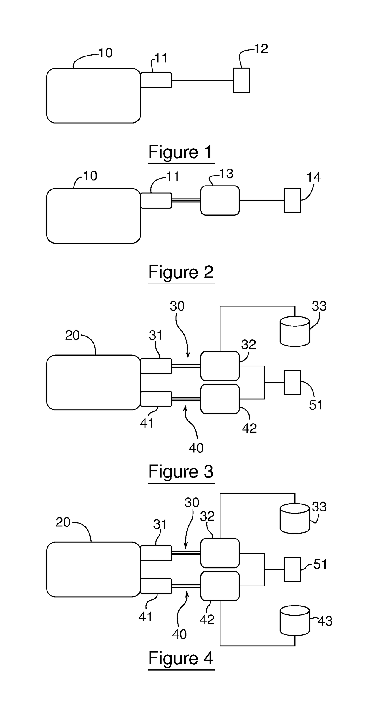
[0059]FIG. 1 is a schematic view of an architecture of a known helicopter propulsion system comprising a turboshaft engine 10 and a system for controlling said turboshaft engine. The control system comprises an electric machine 11 suitable for rotating the turboshaft engine 10 on demand so as to ensure the start-up thereof. The electric machine 11 draws its power directly from a low-voltage onboard network 12 of the helicopter, which is typically a network ...


PUM


Abstract

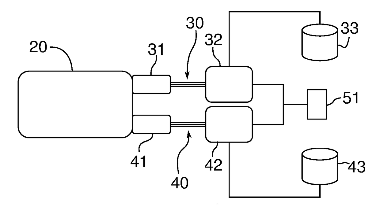
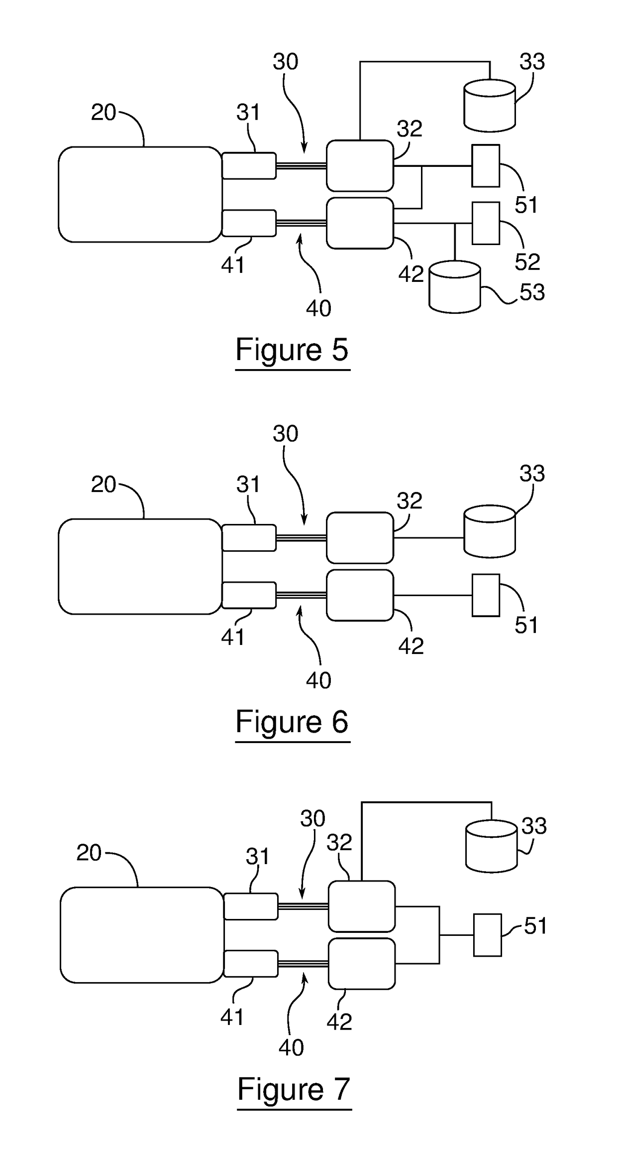
The invention relates to an architecture of a propulsion system of a multi-engine helicopter comprising turboshaft engines connected to a power transmission gearbox, characterised in that it comprises: at least one hybrid turboshaft engine (20) capable of operating in at least one standby mode during a stable cruise flight of the helicopter; at least two systems (30; 40) for controlling each hybrid turboshaft engine (20), each system (30; 40) comprising an electric machine (31; 41) connected to the hybrid turboshaft engine (20) and suitable for rotating the gas generator thereof, and at least one source (33; 43) of electrical power for said electric machine (31; 41), each reactivation system (30; 40) being configured such that it can drive said turboshaft engine (20) in at least one operating mode among a plurality of predetermined modes.

Description

1. TECHNICAL FIELD OF THE INVENTION[0001]The invention relates to an architecture of a propulsion system of a multi-engine helicopter, in particular a twin-engine or three-engine helicopter, and to a helicopter comprising a propulsion system that has such an architecture.2. TECHNOLOGICAL BACKGROUND[0002]As is known, a twin-engine or three-engine helicopter has a propulsion system comprising two or three turboshaft engines, each turboshaft engine comprising a gas generator and a free turbine which is rotated by the gas generator and is rigidly connected to an output shaft. The output shaft of each free turbine is suitable for inducing the movement of a power transmission gearbox, which itself drives the rotor of the helicopter.[0003]It is known that, when the helicopter is in a cruise flight situation (that is, when it is progressing in normal conditions, during all flight phases, except for transitional phases of take-off, ascent, landing or hovering flight), the turboshaft engines ...

Claims


Application Information

Patent Timeline
Patent Type & Authority Applications(United States)
IPC IPC(8): B64C27/14F01D13/00B64D27/24F02C7/36F01D19/00B64D27/02F02C7/268
CPCB64C27/14F01D19/00F01D13/00F02C7/36F05D2270/13F02C7/268B64D2027/026F05D2220/329B64D27/24F01D13/003F05D2220/76Y02T50/60B64C27/12B64D27/10B64D27/026
Inventor VALLART, PHILIPPEBAZET, JEAN-MICHELLE DUIGOU, LOIC
Owner TURBOMECA SA
Learn More