Machine tool control method and machine tool control device

a control method and control device technology, applied in computer control, program control, instruments, etc., can solve the problems of difficult identification of feed axis or movement direction, complex operation of machine tools, etc., and achieve the effect of suppressing erroneous operation and being convenient to opera

Inactive Publication Date: 2017-10-26
MAKINO MILLING MASCH CO LTD
View PDF8 Cites 18 Cited by
  • Summary
  • Abstract
  • Description
  • Claims
  • Application Information

AI Technical Summary

Benefits of technology

[0022]According to the present invention, the control method for the machine tool and the control apparatus for the machine tool can be provided, that enable the machine tool to b...

Problems solved by technology

Along with the increase of machine tool functions, the machine tool operation has become complex and difficult.
However, when the type of the machine tool changes, it is difficult for the operator to identify a feed axis ...

Method used


Image

  • Machine tool control method and machine tool control device
  • Machine tool control method and machine tool control device
  • Machine tool control method and machine tool control device

Examples


Embodiment Construction

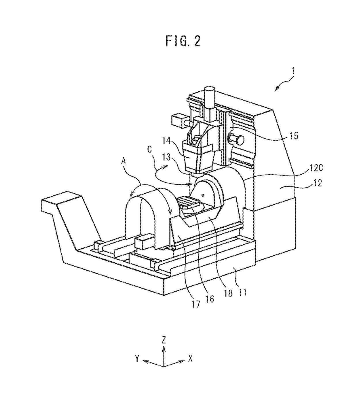
[0043]Referring to FIGS. 1 to 21, a control method for a machine tool and a control apparatus for the machine tool in an embodiment will be described. The machine tool according to the present embodiment is a numerical control type that automatically performs machining on the basis of a machining program by moving a tool relative to the workpiece.

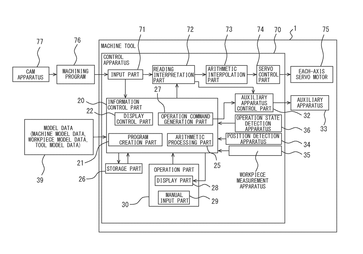
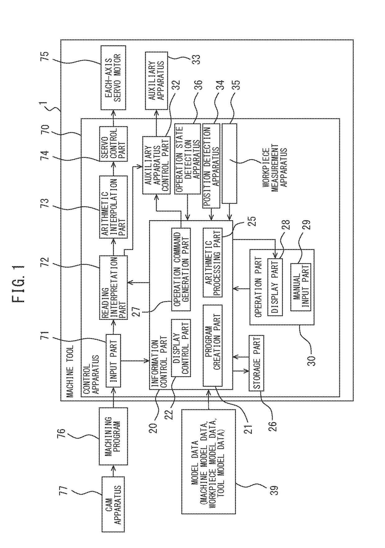
[0044]FIG. 1 shows a block diagram of the machine tool in the present embodiment. The machine tool 1 includes a control apparatus 70. The control apparatus 70 includes, for example, a CPU (Central Processing Unit), a RAM (Random Access Memory), and a ROM (Read Only Memory) interconnected via a bus. The control apparatus 70 includes an input part 71, a reading interpretation part 72, an arithmetic interpolation part 73, and a servo control part 74. When machining by the machine tool 1, a machining program 76 is prepared in advance. The machining program 76 can be created by a CAM (Computer Aided Manufacturing) apparatus 77 or the like on the...


PUM


Abstract

This method of controlling machine tool for machining a workpiece by moving a tool and the workpiece relatively to each other comprises: displaying an image of the machine tool on a display unit, pre-storing a motion of the machine tool corresponding to an operation by an operator with respect to the image of the machine tool; obtaining a content of the operation by the operator with respect to the image of the machine tool; generating an operation command for causing the machine tool to operate according to the operation content; and activating the machine tool on the basis of the operation command.

Description

CROSS-REFERENCE TO RELATED APPLICATIONS[0001]This application is a U.S. National Stage Patent Application of International Application No. PCT / JP2014 / 078519, filed Oct. 27, 2014, which is hereby incorporated by reference in the present disclosure in its entirety.FIELD OF THE INVENTION[0002]The present invention relates to a control method for a machine tool and a control apparatus for the machine tool.[0003]Background of the Invention In a conventional technique, machine tools are known that move tools relative to workpieces in order to perform machining such as cutting. In addition, among such machine tools, a machine tool of a numerical control type that designates a path of the tool on the basis of coordinates or the like of a predetermined feed axis and performs machining while moving the tool with respect to the workpiece is known. By moving at least one of the workpiece and the tool according to an operation command from a control apparatus, the machine tool can automatically ...

Claims


Application Information

Patent Timeline
IPC IPC(8): G05B19/409
CPCG05B19/409G05B2219/34337G05B2219/35134G05B2219/32128
Inventor HOSHINO, YOSHIHIROISHII, KAZUNARIKAWAI, RIEUNNO, TAKAHIROSTANCU, ALEXANDRA FLORENTINA
Owner MAKINO MILLING MASCH CO LTD
Why Eureka
Try Eureka