
Method of 3D panoramic mosaicing of a scene

a technology scene, applied in the field of 3d panoramic mosaicing of scene, can solve the problems of stereoscopic system restoration, difficult calibration of cameras, inaccurate 3d reconstruction,

Inactive Publication Date: 2017-10-26
THALES SA
View PDF0 Cites 5 Cited by
  • Summary
  • Abstract
  • Description
  • Claims
  • Application Information

AI Technical Summary

Benefits of technology

This approach enables robust, accurate, and real-time 3D mosaicing over extensive spatial and angular ranges, suitable for complex scenes, with the ability to handle arbitrary motions and concave objects, producing a complete and conformal textured mosaic without geometric deformations.

Problems solved by technology

This solution exhibits several drawbacks:the cameras are difficult to calibrate (problems of vibration),an inaccuracy in restitution of the 3D reconstruction on account of a stereo base limited by the spacing between the cameras,low-field and low-extent restitution on account of the limited optical field of the cameras.
Moreover, the finalized 3D reconstruction is not obvious, since it is constructed by assembling local 3D reconstructions (resulting from the method of stereoscopic restitution of 2, often small-field, images) which may be very noisy on account of the limited number of images which made it possible to construct it, of the limited field of the cameras and of the fact that the reconstruction planes dependent on the respective attitudes of the cameras have a geometry that is difficult to measure accurately (the relative position and relative geometry of the cameras serving to do the 3D reconstruction is often inaccurate in practice when dealing with cameras which are 1 or 2 meters apart and liable to vibrate with respect to one another: this is still more evident when these cameras are motorized).
Lastly, the stereoscopic system restores poorly planes which are almost perpendicular to one of the 2 cameras (this is the problem of the restitution of pitched roofs in aerial or satellite stereoscopic imaging).
A moving low-field or mean-field camera, but the 3D reconstruction is limited by the path and the orientation of the camera and is therefore not omnidirectional; moreover, the reconstruction may exhibit holes on account of unchecked motions of the camera or non-overlaps of the latter in the course of its motion.
The algorithms used for 3D reconstruction impose a reconstruction in a frame tied or close to the focal plane of the camera, thereby limiting the possibilities of reconstruction (a single principal reconstruction plane and very limited reconstruction when the camera changes orientation).
The result of the reconstruction is also very noisy and may exhibit numerous errors on account of the small overlap between images, of a constant plane of reconstruction of the reconstructed scene (and of a camera that could deviate from this plane) and of the use of algorithms which for the 3D reconstruction utilize only two images separated by a relatively small distance.
The mosaicing obtained by the ground overlaying of the successive images is inoperative and is not conformal when the scene is not flat and / or comprises 3D elements.
Active sensors, that is to say with telemetry, but here again the 3D reconstruction is not omnidirectional and is not necessarily segmented, the measurements being obtained in the form of scatters of points that are difficult to utilize in an automatic manner.
Moreover, the mesh obtained by these active sensors exhibits the drawback of being angularly non-dense (typically fewer than 4 points per m2 for airborne applications at 1 km height).
The technique is not at the moment suitable for being able to produce a textured image of the scene and must almost always be corrected manually.
All the previous solutions are unsuitable for obtaining a 3D mosaicing for a 3D scene of large dimension, that is to say greater than 500 m×500 m. The 3D instantaneous mosaics obtained exhibit deformations and are limited in angular extent (typically <30°) or spatial extent.
The assembling of the mosaics is complex when the terrain is 3D and the final result does not conform to the geometry of the scene.

Method used


Image

  • Method of 3D panoramic mosaicing of a scene
  • Method of 3D panoramic mosaicing of a scene
  • Method of 3D panoramic mosaicing of a scene

Examples


first embodiment

[0145] the 3D reconstruction and the mosaicing are performed in a successive manner after each acquisition; this assumes that a new 3D reference reconstruction has just been performed subsequent to (one or more) 3D reconstructions already performed.

second embodiment

[0146] the 3D reconstruction and the mosaicing are performed in parallel after each acquisition; this assumes that the mosaicing is performed whilst a new 3D reconstruction is still in progress, in which case the 3D reference reconstruction is that performed at one of the previous acquisitions of 2D images, or indeed a 3D reconstruction performed previously.

[0147]These various steps will be described in greater detail.

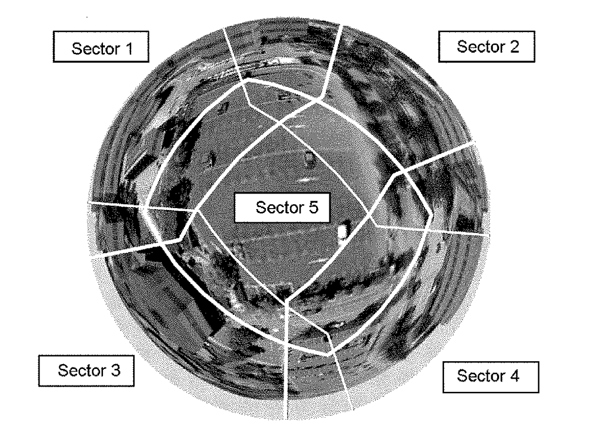
[0148]A) Choosing 3D projection planes (or surfaces).

[0149]This first step consists in choosing the 3D projection planes or surfaces on which the mosaic is constructed. These 3D projection planes or surfaces can be chosen freely by the operator at a given moment of the mosaicing or computed automatically on the basis of the current (or reference) 3D reconstruction of the scene according to predetermined criteria (for example planes parallel to the reconstructed surface of the ground or principal planes extracted from the 3D reconstruction). 3D projection surfaces may a...


PUM


Abstract

A method of 3D mosaicing of a scene as a 3D mosaic, wherein at least one 3D reconstruction having been obtained without a priori information about the scene, in the course of the following steps of:acquisition of successive images by a panoramic sensor moving along an unconstrained 3D reconstruction trajectory, such that the image of at least one point of the scene is in at least 3 successive 2D panoramic images obtained according to various panoramic system-point of the scene directions,rectification of these images on different rectification planes covering different directions, and matching of the rectified images,3D reconstruction on reconstruction planes on the basis of the rectified matched images,the last 2D panoramic acquired image being called current 2D panoramic image,it further comprises the following steps:A) On the basis of the obtained 3D reconstruction and of the current 2D panoramic image, choosing one or more projection surfaces on which the mosaic will be constructed,B) Selecting sectors of the current 2D panoramic image, and selecting textures in the selected sectors by selecting visible parts that is to say that are not hidden by a surface of the scene, with the aid of the 3D reconstruction,C) Projecting the selected textures onto each projection surface and fusing the textures in each projection surface so as to thus obtain a conformal mosaic on each projection surface.

Description

CROSS-REFERENCE TO RELATED APPLICATIONS[0001]This application is a continuation of U.S. application Ser. No. 14 / 646,712, filed on May 21, 2015, which is a National Stage of International patent application PCT / EP2013 / 074277, filed Nov. 20, 2013 which claims priority to foreign French patent application No. FR 1203126, filed on Nov. 21, 2012, the disclosures of which are incorporated by reference in their entirety.FIELD OF THE INVENTION[0002]The field of the invention is that of the 3D mosaicing of a scene on the basis of successive panoramic images of this scene.BACKGROUND[0003]The 3D reconstruction of a scene consists in obtaining, on the basis of successive 2D images of this scene taken from different viewpoints, a so-called 3D reconstructed image such that with each pixel of the reconstructed image, that is to say at any point where the reconstruction declares that there is a scene element, are associated the coordinates of the point of the corresponding scene, defined in a frame...

Claims


Application Information

Patent Timeline
Patent Type & Authority Applications(United States)
IPC IPC(8): H04N5/232G06T7/593G06T3/00H04N5/341G06T7/579G06T7/38G06T3/40H04N13/00
CPCG06T7/593G06T7/579G06T7/38G06T2207/20221G06T2207/10032G06T3/4038G06T3/0018H04N5/23238H04N5/23229G06T2207/10004G06T2200/32H04N2013/0088G06T2207/30181H04N5/3415G06T3/047H04N23/698H04N25/41H04N23/80
Inventor HORAK, RAPHAEL
Owner THALES SA
Learn More