Distillation system

a technology of distillation system and distillation pot, which is applied in the direction of distillation in boiler/still, alcoholic beverage preparation, separation process, etc., can solve the problems of unsatisfactory control system and inability to readily recover energy, and achieve the effect of reducing the energy requirement of the distillation pot still, reducing costs and reducing energy requirements

Active Publication Date: 2017-11-02
GEA WIEGAND
View PDF0 Cites 7 Cited by
  • Summary
  • Abstract
  • Description
  • Claims
  • Application Information

AI Technical Summary

Benefits of technology

[0016]The energy requirement of the distillation pot still can be reduced largely without any loss of quality of the distilled whiskey if the mechanical compressor increases the absolute pressure of the pre-compressed water vapour in relation to the absolute pressure at the separator by a factor of 2 to 3, and / or increases the temperature of the pre-compressed water vapour to more than 100° C. Accordingly, it is advantageous if the steam jet pump increases the absolute pressure of the post-compressed water vapour in relation to the absolute pressure of the pre-compressed water vapour by a factor of 1.1 to 1.4, in particular 1.2 to 1.3, and / or increases the temperature of the postcompressed water vapour in relation to the temperature of the pre-compressed water vapour by a factor of 1.05 to 1.3, in particular by a factor of 1.1 to 1.25. The above values apply in particular if the speed of the mechanical compressor is at least 60,000 1 / min (RPM), as described below.
[0017]The mechanical compressor is preferably a rotary blower or a roots blower or a turbo compressor. The rotary blower and also the steam jet pump constitute “volumetric flow conveyors”, which convey a constant volumetric flow in a first approximation, and specifically substantially irrespective of the intake pressure. The system consisting of the rotary blower and steam jet pump can be controlled in an open-loop or closed-loop manner, expediently in this manner in terms of a constant mass vapour flow. In addition, rotary blowers are relatively inexpensive. When using a turbo compressor, its speed is preferably more than 20,000 1 / min (RPM), in particular more than 60,000 1 / min (RPM) and preferably at least 90,000 1 / min (RPM).
[0018]Conventional turbo compressors, as used for energy recovery in distillation or vaporising systems, are relatively expensive. They usually comprise a housing, welded together from sheet metal blanks, and their compressor wheel is also welded together from individual parts. The costs can be reduced considerably if the turbo compressor comprises a housing designed as a cast metal part and a compressor wheel designed as a milled part which is driven by an electric motor using a gear system, in particular a planetary gear system. Such components can be provided cost-effectively, provided their dimensions are relatively small. Such turbo compressors still supply a sufficiently high mass flow rate if they operate at a speed of at least 60,000 1 / min (RPM), preferably at least 90,000 1 / min (RPM), as described above. When using turbo compressors of this kind, compressor units can be reverted to, such as those used in large numbers at relatively low cost as “turbochargers” in internal combustion engines.
[0019]The concept described above, of using the compressor unit of a “turbocharger” of an internal combustion engine as the mechanical compressor of a distillation system, can be used advantageously not only for the pot still distillation system described above but also for distillation systems or vaporising systems of a general nature. The concept therefore also has independent inventive importance, in particular in the case of a distillation system having a distillation apparatus which removes a liquid having a low boiling point, in particular alcohol, from a blend of liquids formed by a plurality of liquids having different boiling points, in particular from a fermented blend of liquids, which distillation apparatus has a mechanical compressor for increasing the pressure and / or the temperature of steam or vapours in the distillation system. It is also preferably provided in this distillation system for the mechanical compressor to have a compressor wheel which is driven at a speed of 90,000 1 / min (RPM) or more. The mechanical compressor is driven by one, if applicable even by more than one, electric motor, which drives the compressor wheel via a gear system, in particular an epicyclic gear system, specifically a planetary gear system. The planetary gear system has at least three gear elements which are coaxial with one another and are rotatable relative to one another about a common axis: sun gear, ring gear and planet carrier for planet gears connected to the sun gear and the ring gear. One feature of the planetary gear is that rotary power supplied to two of said gear elements is transferred to the third gear element additively or subtractively, relative to the speed and / or torque. In a preferred embodiment, it is therefore provided for the compressor wheel to be connected to one of the gear elements of the planetary gear system while one of the two other gear elements is connected to the electric motor, preferably each of the two other gear elements is connected to separate electric motors. When the gear element connected to the compressor wheel, for example, the sun gear, is selected appropriately, the speeds of the two electric motors can be superimposed on one another additively. This concept is also of particular advantage for the pot still distillation system described above.

Problems solved by technology

Energy recovery is not readily possible since the evaporation temperature in the distillation pot still rises with increasing alcohol depletion of the alcoholic liquid in the pot still, just as the condensation temperature of the alcoholic vapours rises.
A control system is not desirable since every change in the process parameters can have an influence on the quality of the whiskey being produced.

Method used


Image

  • Distillation system
  • Distillation system

Examples


Embodiment Construction

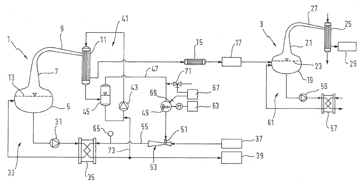
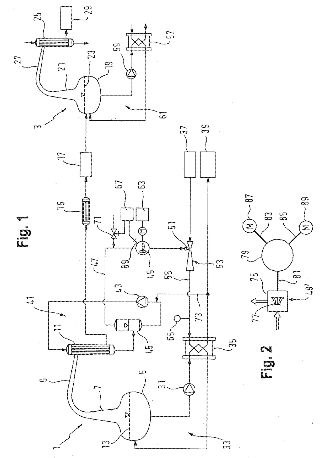
[0023]FIG. 1 shows a pot still distillation system for whiskey having two distillation pot stills 1, 3 distilling an alcoholic liquid in portions in two successive distillation stages. The distillation pot still 1 (wash still), which is assigned to the first distillation stage, consists of copper and has a base 5, which is covered at the top by a helmet-like, tapering top 7 and is connected to a condenser 11 by means of an arm 9 (lyne arm), which condenser condenses the alcoholic vapours which rise up when the alcoholic liquid 13 located in the base is heated. The alcoholic liquid 13 is fermented wort (wash), which is heated up in a manner described below, and the vapours of which condense on the top 7, the arm 9 and in the present case, on external surfaces of a bundle of pipes, likewise consisting of copper, of the condenser 11. The condensate (low wines) of the first distillation stage is supplied via a cooler 15 to a storage tank 17 from which the distillation pot still 3 for th...


PUM

PropertyMeasurementUnit
temperatureaaaaaaaaaa
pressureaaaaaaaaaa

Abstract

A pot distillation system, in particular for whiskey, includes a distillation bubble with a base equipped to heat an alcoholic liquid, and a top removing alcohol vapors. The alcoholic liquid in the base is heated by a heating unit having a heat exchanger which is in thermal contact with the alcoholic liquid and heated by water vapor. A condenser having a cooling water circuit recirculating cooling water across the condenser condenses the alcohol vapor supplied from the top. The cooling water circuit includes a separator which removes water vapor from the cooling water circuit. The water vapor removed by the separator is pre-compressed in a mechanical compressor and supplied to an intake port of a steam jet pump which is driven by water vapor from a water vapor source and which further compresses the pre-compressed water vapor, and the steam jet pump supplying the further compressed water vapor to the heat exchanger for heating same.

Description

BACKGROUND[0001]The invention relates to a distillation system, in particular a pot still distillation system, preferably for potable alcohol and specifically, whiskey.BRIEF DESCRIPTION[0002]Even though potable alcohol can also be separated into fractions in continuously operating distillation systems, distillation in portions in pot still distillation systems is used to a large extent for some types of potable alcohol, especially, however, for whiskey. In the pot stills, which largely consist of copper, the wort, which has been fermented to make an alcoholic liquid (wash) by adding yeast, is heated up in a tank-like base of the pot still, whereby alcohol vaporises out of the fermented liquid. The base of the pot still is covered by a conical top and connected to a condenser, which condenses alcohol vapour rising out of the base.[0003]Normally, whiskey is distilled in at least two pot stills arranged in succession. In addition to the raw alcohol, the fermented liquid (wash) to be di...

Claims


Application Information

Patent Timeline
Patent Type & Authority Applications(United States)
IPC IPC(8): B01D3/00B01D3/02B01D3/42C12H6/02
CPCB01D3/003B01D3/42B01D3/02B01D3/007C12H6/02
Inventor MOSSLEIN, MONIKASCHEIBY, DAVID
Owner GEA WIEGAND
Why Eureka
Try Eureka