Head-mounted displaying of magnified images locked on an object of interest

a technology of magnified images and objects, applied in the field of head-mounted displays, magnification optics, medical imaging, image processing, and display presentation, can solve the problems of obstructing the peripheral vision of the user, cumbersome handling of loupes, and obstructing the user's peripheral vision, so as to selectively reduce the transparency of at least a portion of the display area, increase or decrease the magnification factor of the displayed image, and increase the angular resolution

Active Publication Date: 2017-11-02
ELBIT SYST LTD
View PDF2 Cites 53 Cited by
  • Summary
  • Abstract
  • Description
  • Claims
  • Application Information

AI Technical Summary

Benefits of technology

[0010]In accordance with one aspect of the present invention, there is thus provided a system for presenting magnified images locked onto an object of interest in the environment of an operator. The system includes at least one camera, a head tracker, a processor, and a head-mounted display (HMD). The camera is disposed on the head of the operator such that the camera moves in conjunction with the head of the operator. The processor is coupled with the camera, the head tracker, and the HMD. The HMD is worn by the operator. The camera is configured to acquire a sequence of image frames of a scene. The head tracker is configured to detect the line-of-sight (LOS) of the operator by detecting at least the orientation of the head of the operator. The processor is configured to obtain designated coordinates of at least one object of interest in the scene, to determine the relative angle between the detected operator LOS and the object of interest, and to determine the coordinates of the object of interest in the acquired image frames. The processor is further configured to apply image processing for fine stabilization of the image frames based on at least one previous image frame so as to at least compensate for head movements of the operator, and to rescale a region surrounding the object of interest in the image frames, in accordance with at least one display parameter, to produce respective magnified image frames of the object of interest. The HMD is configured to display the magnified image frames to the operator such that the object of interest appears in a defined position on the display regardless of the head movements of the operator. The processor may be further configured to apply image or signal processing for coarse stabilization of the image frames, based on the detected LOS of the operator. The processor may be further configured to crop the region surrounding the object of interest in the image frame prior to rescaling. The processor may be further coupled with a secondary imaging device, configured to acquire secondary image frames including the object of interest. The processor may be further configured to determine the coordinates of the object of interest in the secondary image frames, and the HMD may be further configured to selectively display the secondary image frames to the operator. The HMD may display the secondary image frames in conjunction with the magnified image frames from the camera. The system may further include a user interface, configured to receive instructions from the operator. The instructions may include: a designation of the object of interest in the imaged scene; an indication to switch views or change the imaging source of the displayed image; a designation of the display parameter; and / or an indication to increase or decrease the magnification factor of the displayed image. The user interface may be integrated with the head tracker, allowing the user to provide the instructions via head movements. The HMD may display the magnified image frame such that the object of interest appears superimposed at its true geolocation, in relation the LOS of the operator. The HMD may be configured to display supplementary content overlaid onto the magnified image frames displayed by the HMD. The supplementary content may appear magnified in relation to the magnification of the object of interest in the magnified image frame. The camera may be configured to acquire the sequence of image frames at an increased angular resolution relative to human vision angular resolution. The camera may include a plurality of cameras, where the HMD is configured to display a different image toward each eye of the operator, providing a stereoscopic view of the object of interest. The processor may be further configured to determine the distance between the operator and the object of interest, and to adjust the magnified image frame in accordance with the determined distance. The processor may be further configured to track multiple objects of interest in the acquired image frames, and to generate a plurality of magnified image frames respective of each object of interest, where the HMD is further configured to selectively display at least one of the generated magnified image frames. The system may further include an eye tracker coupled with the processor, the eye tracker configured to detect the gaze direction of the operator, where the LOS of the operator is further determined in accordance with the detected gaze direction. The camera may include: a CMOS or CCD camera; a visible light camera; an IR or NIR camera; a digital camera; a video camera; and / or a camera with an adjustable optical magnification setting. The HMD may include a transparent display, configured to present a displayed image while allowing a see-through view of the scene in the operator FOV. The transparent display may be configured to selectively reduce the transparency of at least a portion of the display area while presenting a displayed image. The camera and the HMD may be aligned along a common optical axis. The HMD may be further configured to provide a notification of an obstruction of the object of interest, or to provide a notification of the object of interest exceeding the FOV of the camera. The system may further include an illuminator, configured to illuminate the object of interest in accordance with the operator LOS.
[0011]In accordance with another aspect of the present invention, there is thus provided a method for presenting magnified images locked onto an object of interest in the environment of an operator. The method includes the procedure of acquiring a sequence of image frames of a scene, using at least one camera disposed on the head of the operator such that the camera moves in conjunction with the head of the operator. The method further includes the procedure of detecting the LOS of the operator by detecting at least the orientation of the head of the operator. The method further includes the procedures of designating coordinates of at least one object of interest in the scene; determining the relative angle between the detected operator LOS and the object of interest; and determining the coordinates of the object of interest in the acquired image frames. The method further includes the procedures of applying image processing for fine stabilization of the image frames based on at least one previous image frame so as to at least compensate for head movements of the operator; and rescaling a region surrounding the object of interest in the image frames, in accordance with at least one display parameter, to produce respective magnified image frames of the object of interest. The method further includes the procedure of displaying the magnified image frames on an HMD worn by the operator, such that the object of interest appears in a defined position on the display regardless of the head movements of the operator. The method may further include the procedure of applying image or signal processing for coarse stabilization of the image frames, based on the detected LOS of the operator. The method may further include the procedure of cropping the region surrounding the object of interest in the image frame prior to rescaling. The method may further include the procedures of acquiring secondary image frames that include the object of interest, using at least one secondary imaging device; and displaying the secondary image frames on the HMD. The display parameter may include: a magnification factor; a FOV of the displayed image frame; a relative location of the displayed image frame on the HMD; and / or selected ranges for contrast, sharpness and / or brightness of the displayed image frame. The procedure of acquiring a sequence of image frames may include acquiring a sequence of image frames at an increased angular resolution relative to human vision angular resolution. The procedure of displaying the magnified image frames on a HMD may include displaying a different image toward each eye of the operator, providing a stereoscopic view of the magnified object of interest. The procedure of detecting the LOS of the operator may further include detecting the gaze direction of the operator. The method may further include the procedures of providing a notification of an obstruction of the object of interest, or providing a notification of the object of interest exceeding the FOV of the camera. At least one of the method procedures may be performed iteratively.

Problems solved by technology

However, such a configuration may distract the user and obstruct his peripheral vision.
Handling the loupes can be cumbersome and provide surplus weight when worn by or affixed to the user.
The loupes are also prone to falling off, breaking, and degradation over time.
In addition, a standard loupe typically provides a magnification factor of about 4-5×, which may be insufficient when needing to examine extremely minuscule objects.
Moreover, since each loupe is associated with a fixed magnification factor, it is not possible for a user to selectively adjust the desired magnification according to the particular usage, without replacing it with a different loupe entirely.
A wearable camera or wearable display may be subject to vibrations and movements which can cause eye fatigue, nausea, and disorientation, precluding the user from being able to distinguish small details in the image and thus decreasing the effective resolution.
These vibrations, caused by small and large head movements, can result in linear and rotational displacement of the image, which may significantly alter which content remains viewable within the image.
However, the head movements and camera vibrations diminish the user's ability to maintain focus on small details of the object.
In particular, when the images projected onto the display are magnified, the effects of the head and camera movements are amplified in the resultant image vibrations.

Method used


Image

  • Head-mounted displaying of magnified images locked on an object of interest
  • Head-mounted displaying of magnified images locked on an object of interest
  • Head-mounted displaying of magnified images locked on an object of interest

Examples


Embodiment Construction

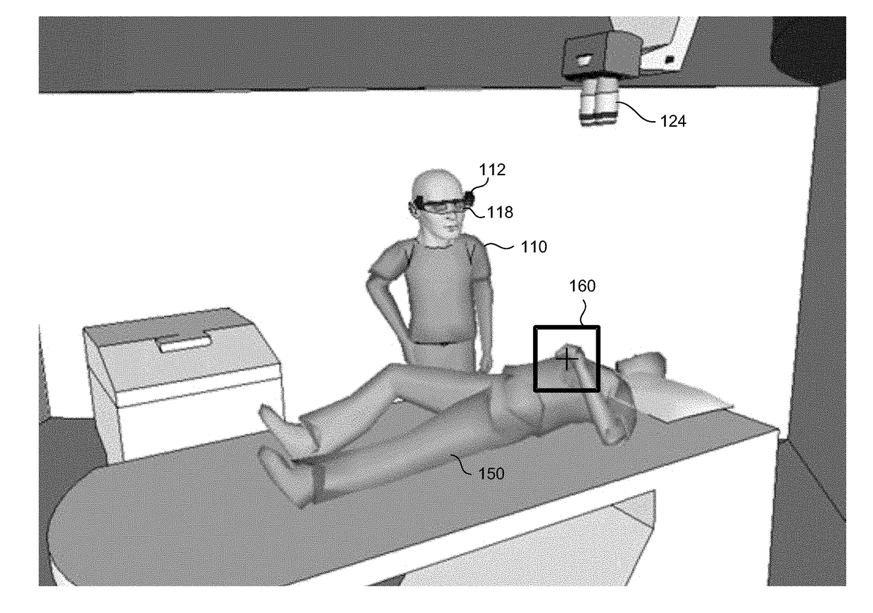
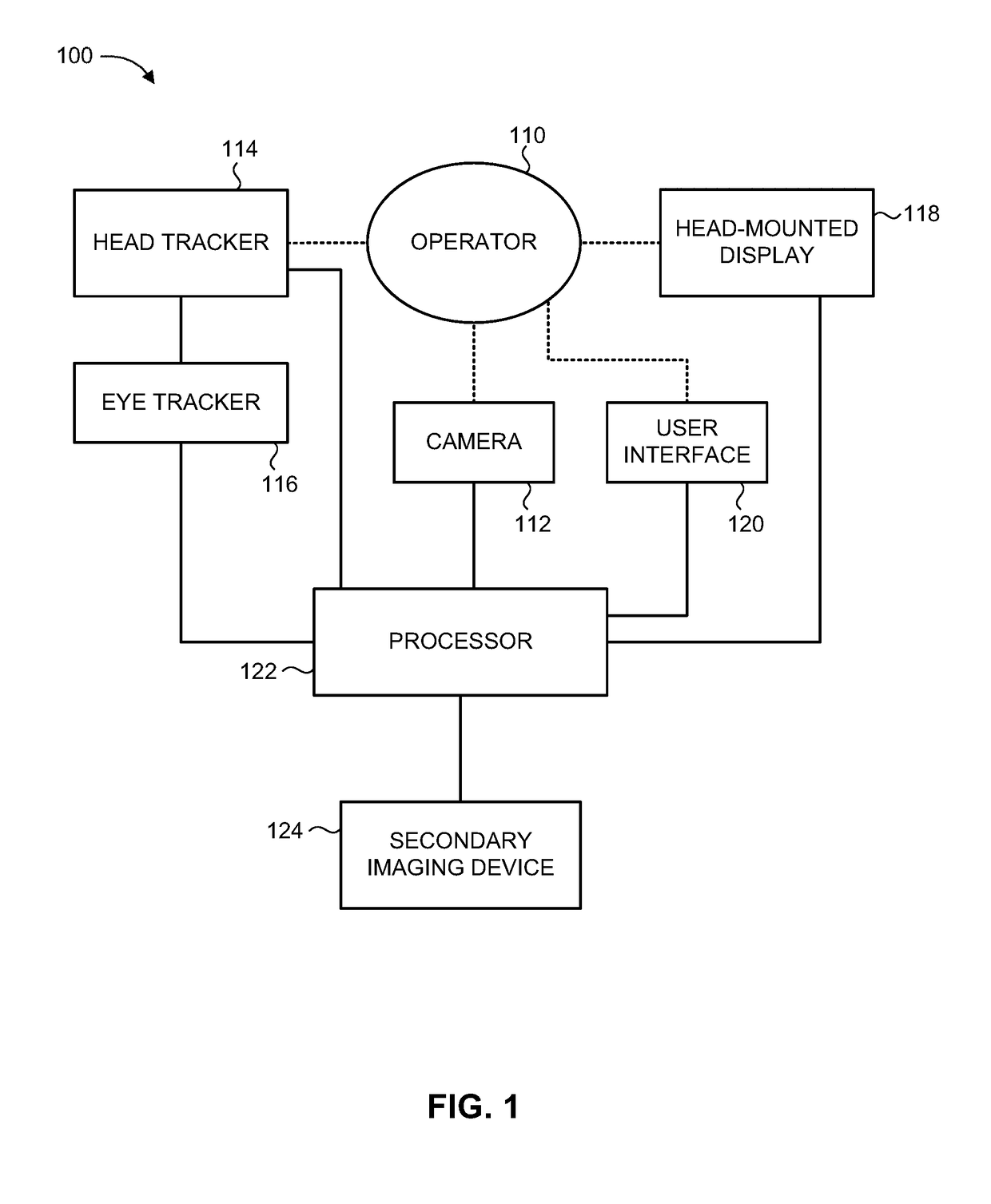
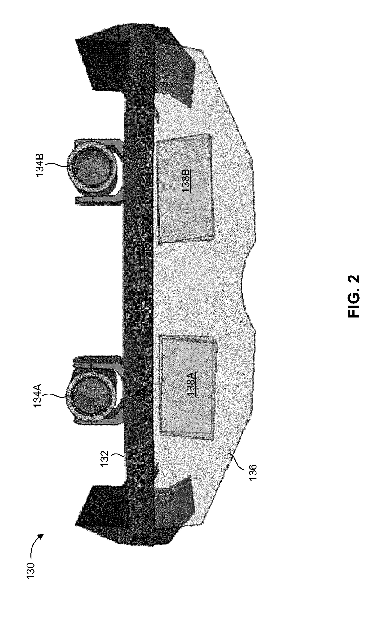
[0022]The present invention overcomes the disadvantages of the prior art by providing a system and method for displaying to a user a magnified image of a view seen through a head-mounted display (HMD), where the magnified image is based on an image captured by at least one head-mounted camera directed to a field of view conforming to the head direction or line-of-sight (LOS) of the user. The system may present a sequence of magnified image frames which remains locked on an object of interest viewable by the user, as determined in relation to the current user head direction or LOS. The image locking displays the object of interest in a pre-defined position on the display, regardless of the head movements of the user. The magnified image may also undergo image stabilization, such that a stabilized view of the object of interest is displayed to the user. The user may adaptively select relevant parameters and settings as required, such as designating a new object of interest, or adjusti...


PUM


Abstract

System and method for presenting magnified images locked onto object of interest in operator environment. A camera disposed on head of operator captures images of scene, where camera moves in conjunction with head movements. A head tracker detects the operator LOS by detecting at least head orientation. A processor obtains designated coordinates of object of interest in scene, and determines relative angle between detected operator LOS and object. The processor determines coordinates of object in acquired images, and applies image processing for fine stabilization of images based on previous images so as to compensate for operator head movements. The processor rescales an image region surrounding object of interest, in accordance with at least one display parameter, to produce respective magnified image frames of object. A head-mounted display displays the magnified images to operator such that object of interest appears in a defined position on display regardless of operator head movements.

Description

FIELD OF THE INVENTION[0001]The present invention generally relates to the fields of head-mounted displays, magnification optics, medical imaging, image processing, and display presentation.BACKGROUND OF THE INVENTION[0002]An optical loupe is a small magnification device with a set of lenses through which a user can view an enlarged appearance of a scene under examination, thereby allowing the user to clearly distinguish small details in the scene. Such magnification devices are widely used in a variety of applications and technical fields, ranging from photography, printing and jewelry, to medicine and dentistry. For example, when performing a medical procedure, such as a surgical operation (e.g., heart surgery, brain surgery, plastic surgery), the medical practitioner may use at least one loupe in order to magnify the treatment area. In particular, two separate loupes may be applied to each eye. The loupe(s) may be held by the user and positioned near his eye only when required, o...

Claims


Application Information

Patent Timeline
Patent Type & Authority Applications(United States)
IPC IPC(8): H04N5/262H04N5/272H04N5/232G06T11/60G06K9/32G06K9/00G02B27/01H04N13/04G02B27/00
CPCH04N5/2628H04N5/23267G06K9/3233G06K9/00664G02B27/0093G06T11/60H04N13/044G02B27/0172H04N5/272G02B27/017G03B15/14G02B30/34G06V20/10H04N23/683H04N13/344
Inventor SCHNEIDER, RONZEITOUNY, ABRAHAM
Owner ELBIT SYST LTD
Why Eureka
Try Eureka