
Impact sensor

a sensor and impact technology, applied in the field of impact sensors, can solve the problems of inability to deploy safety devices at all, impede detection efficiency, and no safety device can be deployed at all, and achieve the effect of fast and reliable detection and easy integration into various vehicles

Active Publication Date: 2017-11-09
IEE INT ELECTRONICS & ENG SA
View PDF26 Cites 2 Cited by
  • Summary
  • Abstract
  • Description
  • Claims
  • Application Information

AI Technical Summary

Benefits of technology

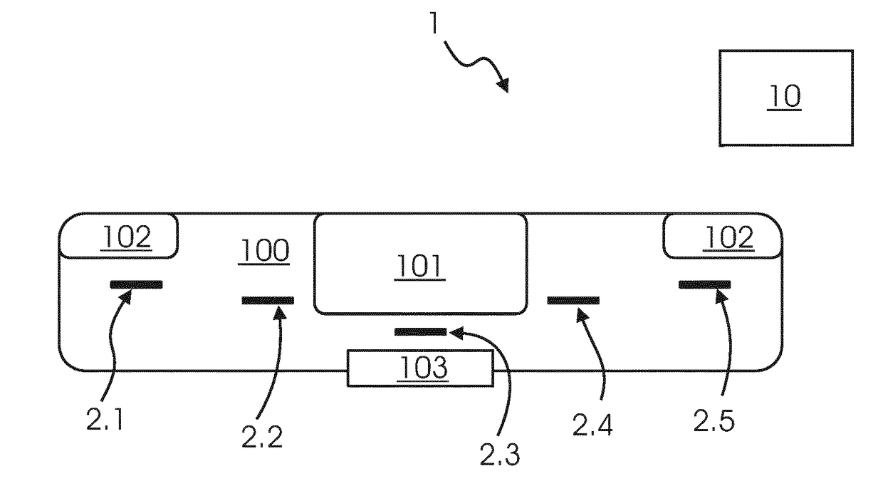
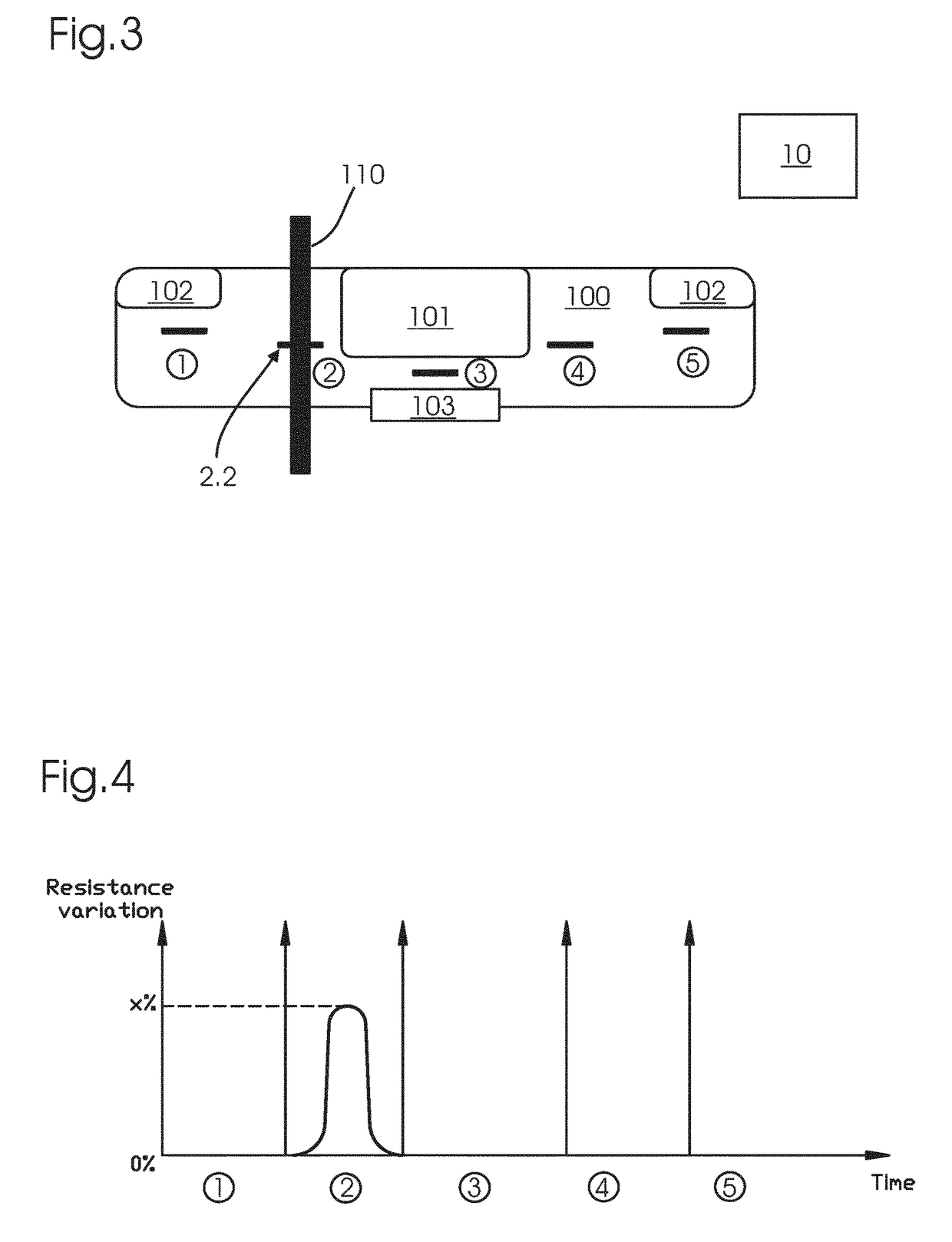
The present invention provides a solution for detecting impacts quickly and reliably in vehicles. The invention is based on the use of metal-containing carbon materials as impact sensors, which are known to have a resistance that changes when they are subjected to strain. These sensors are fast-reacting, easy to measure, and have little or no dependency on temperature or humidity. The sensor material can be made in a small size, allowing for easy integration into various areas of the vehicle. The invention also includes a crash detection system that comprises an exterior component, such as the front or rear bumper of a car, where the impact sensors can be placed. This allows for early detection of impacts and helps to reduce damage and injury in the event of a collision.

Problems solved by technology

Although such sensor elements are well proven in various automotive applications, their detection efficiency is meanwhile hampered due to mechanically softer materials and design constraints of modern car front-ends in order to fulfil requirements related to pedestrian protection or energy savings.
However, a large sensor that may not be curved gives rise to integration problems.
In such a case, no safety device may be deployed at all.

Method used


Image

  • Impact sensor
  • Impact sensor
  • Impact sensor

Examples


Embodiment Construction

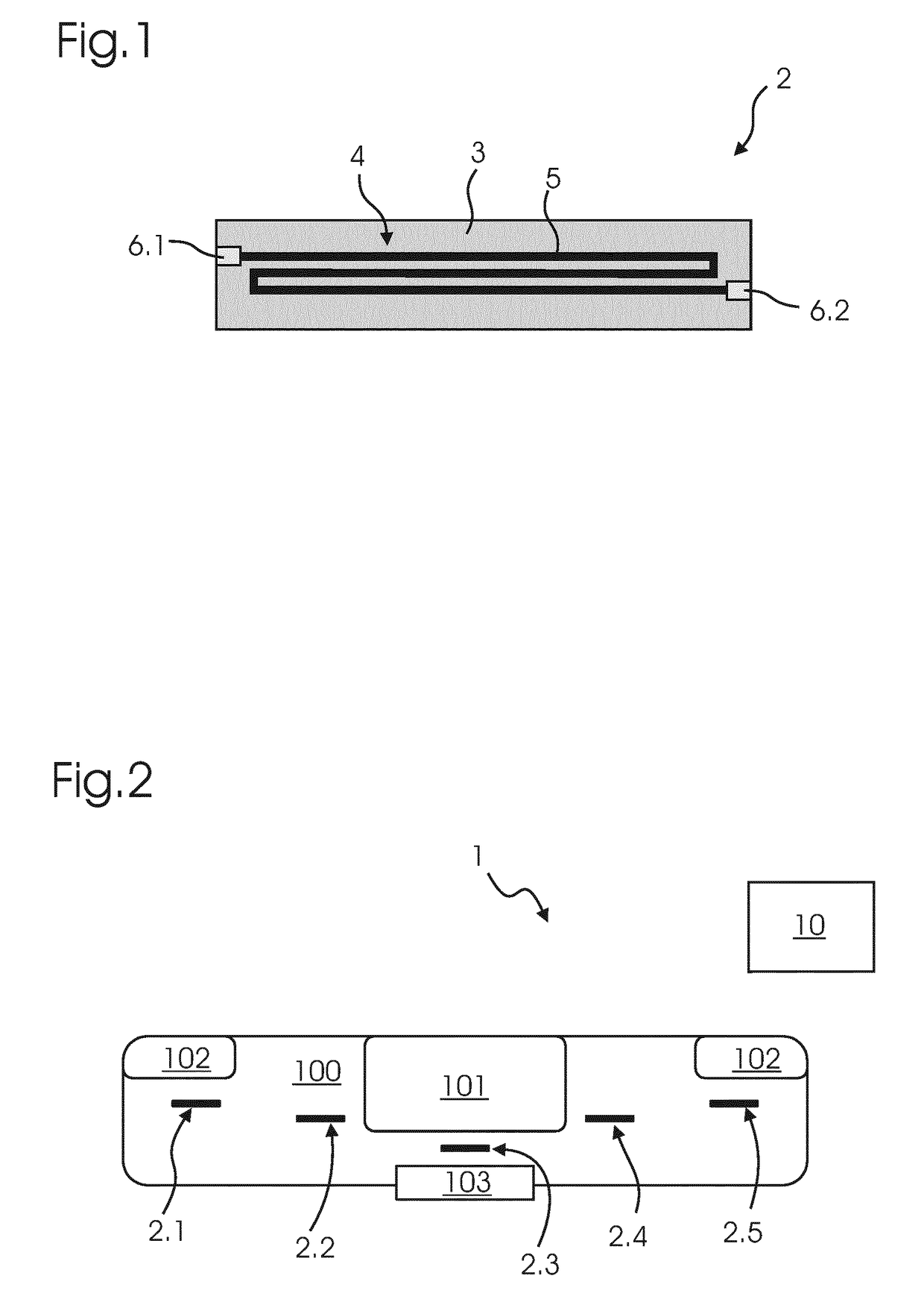
[0037]FIG. 1 shows a schematic view of an impact sensor 2 according to an embodiment of the present invention. The impact sensor 2 is generally rectangular in shape having a length of approximately 100 mm and a width of 15 mm. It is understood, though, that the size and the shape of the impact sensor 2 could be varied. The shape is generally given by a rectangular polymer sheet 3, which has a thickness of 100 μm. In the embodiment shown, the polymer sheet 3 is made of polyimide. On this polymer sheet 3, a layer of sensor material 5 is disposed. The sensor material 5 is Nickel-containing hydrogenated amorphous carbon (Ni:a-C:H), which has been disposed on the polymer sheet 3 by sputtering. The thickness of the layer of sensor material 5 is about 60 nm. The sensor material 5, which is part of a strain-sensitive sensor element 4, is electrically connected between two terminals 6.1, 6.2. These terminals 6.1, 6.2 are made of silver ink and have been disposed on the polymer sheet 3 by scr...


PUM


Abstract

An impact sensor for a vehicle. The impact sensor includes at least one strain-sensitive sensor element which comprises a sensor material, and at least two terminals, between which the sensor material is electrically connected. The sensor material is a metal-containing carbon material.

Description

TECHNICAL FIELD[0001]The invention relates to an impact sensor, to an impact detection system and to a method for impact detection.BACKGROUND ART[0002]Due to more restrictive safety regulation requirements and general market development trends, automotive industry have to establish more efficient passenger and pedestrian protection systems by means of improved active safety devices (e.g. multiple airbag solutions, more sophisticated restraint systems, adapted system deployment strategies, etc.). In general, such techniques needs to more lead time to be activated in order to provide the full protection capability and / or additional data to be deployed in a more dedicated way according to the crash situation. In case of a collision event it is therefore essential to identify strong impacts as early as possible, i.e. in best case at the time of first contact with the car bumper.[0003]Up to now, impact characterization is accomplished by so-called up-front sensors (also known as “g-senso...

Claims


Application Information

Patent Timeline
IPC IPC(8): G01L5/00H01L41/18G01P15/12G01P15/08G01L1/20G01L1/18G01L1/16H01L41/37B81B7/02
CPCG01L5/0052G01L1/16G01L1/18G01L1/20G01P15/08H01L41/183B81B7/02G01P15/123H01L41/37G01P15/122H10N30/092H10N30/852
Inventor PELT, THOMASBOUR, CHRISTIAN
Owner IEE INT ELECTRONICS & ENG SA
Learn More