Supercharge Your Innovation With Domain-Expert AI Agents!

Integrated system and method for testing system timing margin

a timing margin and integrated system technology, applied in the direction of generating/distributing signals, pulse automatic control, instruments, etc., can solve the problems of critical timing errors, limited laboratory testing to conditions, and time-consuming and labor-intensive problems

Active Publication Date: 2017-11-09
HAMILTON SUNDSTRAND CORP
View PDF0 Cites 6 Cited by
  • Summary
  • Abstract
  • Description
  • Claims
  • Application Information

AI Technical Summary

Benefits of technology

The patent is about a built-in test circuit for testing the timing of a processing device. The circuit includes a first clock circuit that generates a main clock signal, a second clock circuit, and a logic circuit. The second clock circuit generates an asynchronous clock signal that is used to determine the timing margin of the processing device. The logic circuit processes the main and second clock signals and outputs a third clock signal that is used to synchronize the operation of the processing device. The second clock circuit maintains a steady value when the processing device is in normal operation and the clinical effect of the patent is to provide a reliable and effective method for testing the timing margin of a processing device.

Problems solved by technology

However, with timing margins reaching the order of sub nS, such timing errors have become critical.
However, each unit has its own particular sources of errors and delays and noise signature such that timing margin limits may be unique to each unit.
Methods for testing for system timing margins have also been attempted using connectors to couple each unit to testing equipment, however the connectors themselves can introduce timing error.
Additionally, laboratory testing is limited to conditions at the time at which the test is performed.
However, once a unit is removed from the laboratory, conditions that the unit is exposed to, such as changes in temperature, may affect the unit's system timing margin.

Method used


Image

  • Integrated system and method for testing system timing margin
  • Integrated system and method for testing system timing margin
  • Integrated system and method for testing system timing margin

Examples


Embodiment Construction

[0024]Embodiments of the disclosure include a built-in test circuit, a processing device with an integrated built-in test circuit for determining system timing margins, and methods of determining system timing margins of a processing device.

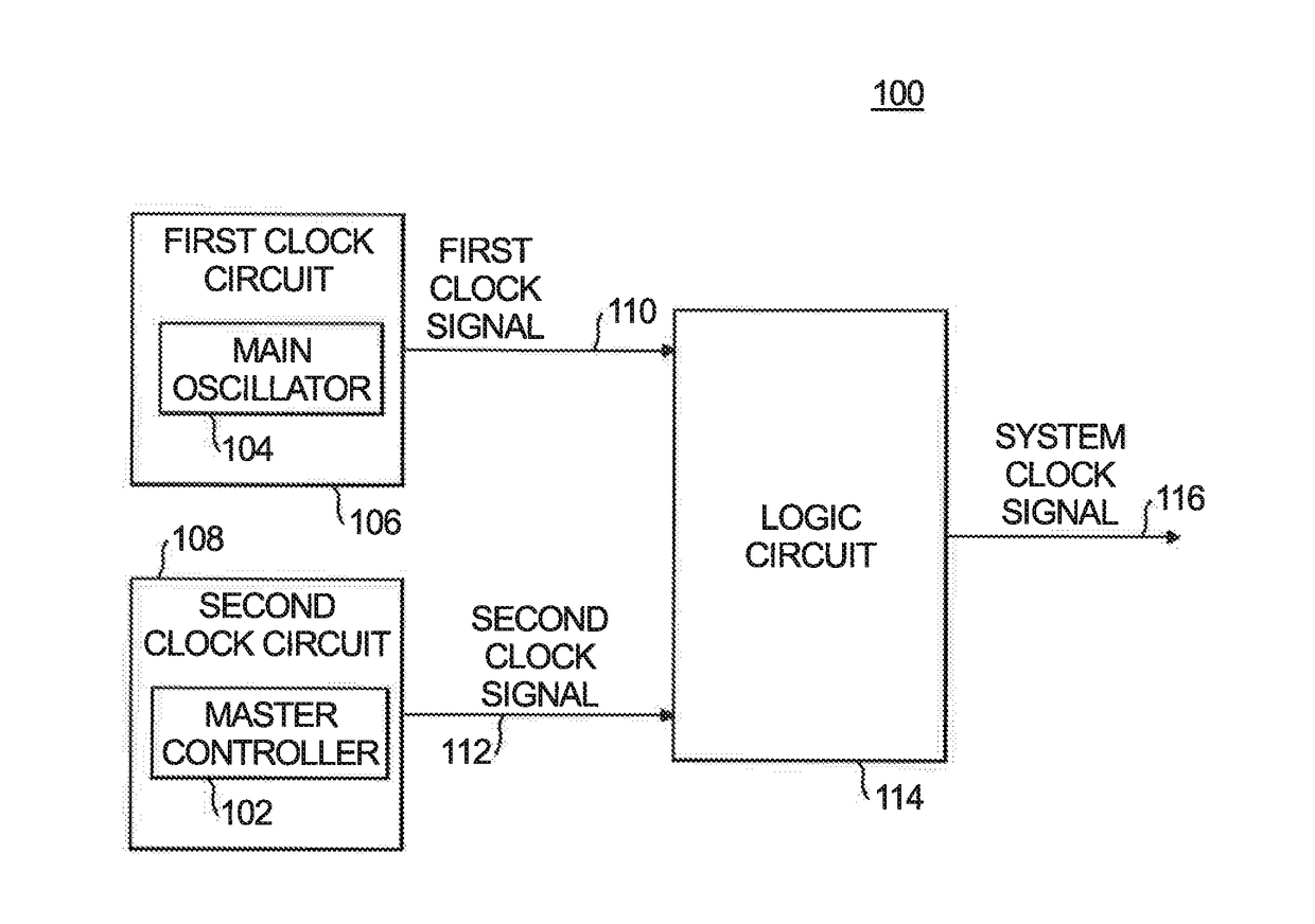
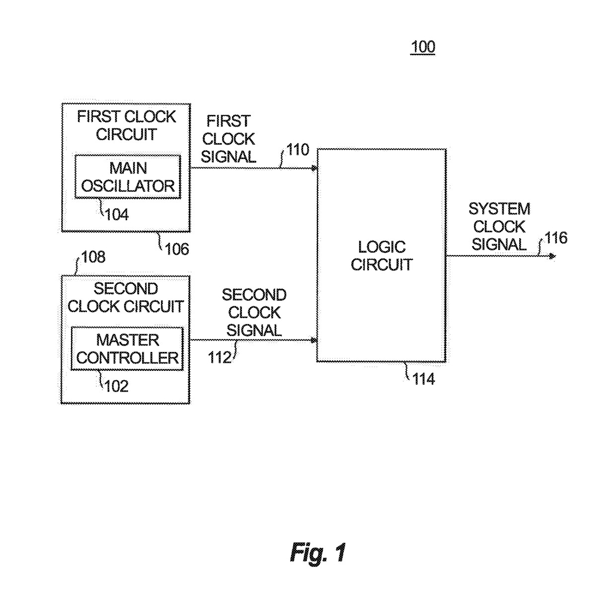
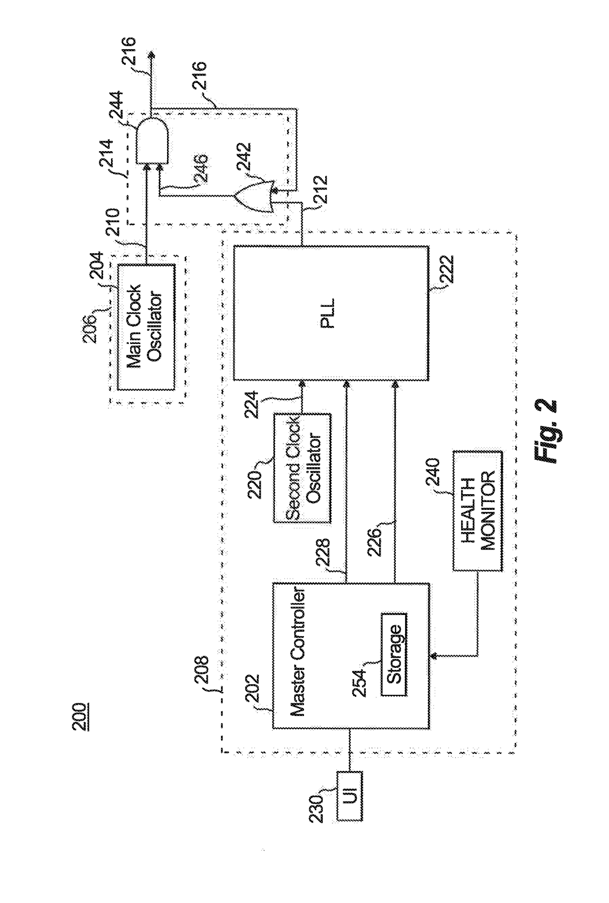
[0025]Reference will now be made to the drawings wherein like reference numerals identify similar structural features or aspects of the subject disclosure. For purposes of explanation and illustration, and not limitation, a block diagram of an exemplary embodiment of a processing device with a built-in test circuit in accordance with the disclosure is shown in FIG. 1 and is designated generally by reference character 100. Other embodiments of built-in test circuits in accordance with the disclosure, or aspects thereof, are provided in FIGS. 2-6, as will be described. A processing device 100 with a built-in test circuit is shown in FIG. 1. The built-in test circuit is integrated with the processing device 100. The term “integrated with,” as used h...


PUM


Abstract

A built-in test circuit for testing a system timing margin of a processing device under-test is provided. The processing device includes a controller and first clock circuit, wherein the first clock circuit generates a first clock signal and the first clock signal is a main clock signal provided for operation of the processing device. The built-in test circuit includes a second clock circuit and a logic circuit, both of which are integrated with the processing device. The second clock circuit generates a second clock signal. The logic circuit processes the first and second clock signals and outputs a third clock signal. The third clock signal is used to determine system timing margin of the processing device.

Description

BACKGROUND OF THE DISCLOSURE1. Field of the Invention[0001]The present disclosure relates to a method and test circuit for testing system timing margin of a processing system, and more particularly to a method and built-in test circuit that is integrated into the processing system for testing the system timing margin of the processing system.2. Description of Related Art[0002]The clock speeds of processing systems have been increasing over time. Conventionally, timing analyses were not concerned with sources of small timing error, such as jitter. However, with timing margins reaching the order of sub nS, such timing errors have become critical.[0003]Attempts to determine timing margins have traditionally been performed on a single production unit that serves as a sample unit for a batch of units. However, each unit has its own particular sources of errors and delays and noise signature such that timing margin limits may be unique to each unit. Methods for testing for system timing m...

Claims


Application Information

Patent Timeline
IPC IPC(8): G06F1/14G06F1/06
CPCG06F1/06G06F1/14G01R31/31922H03L7/16G06F1/08G01R31/31727
Inventor LILLESTOLEN, KIRK A.HESS, GARY L.
Owner HAMILTON SUNDSTRAND CORP
Features
  • R&D
  • Intellectual Property
  • Life Sciences
  • Materials
  • Tech Scout
  • Unparalleled Data Quality
  • Higher Quality Content
  • 60% Fewer Hallucinations
Learn More