
Incorporated device and method for controlling incorporated device

a technology of incorporated devices and incorporated cells, which is applied in the direction of electrochemical generators, instruments, water/sewage treatment by electrochemical methods, etc., can solve problems such as heat generation in electrolytic cells, and achieve the effects of suppressing the temperature suppressing the reduction in the life of electrodes, and suppressing the rise in electrolytic cells

Inactive Publication Date: 2017-11-09
MORINAGA MILK IND CO LTD
View PDF4 Cites 2 Cited by
  • Summary
  • Abstract
  • Description
  • Claims
  • Application Information

AI Technical Summary

Benefits of technology

The present invention provides an incorporated device that includes an electrolytic cell and a power control device capable of stopping the supply of electrolysis current when the environmental temperature is outside the set ratios, and resuming it when the temperature is within the range. This helps to prevent damage to the electrodes and extend the lifespan of the device without measuring the temperature of the cell. The method for controlling the incorporated device is also provided.

Problems solved by technology

In the case of electrolysis in an electrolytic cell, there is a problem of heat generation in the electrolytic cell when operated continuously.

Method used


Image

  • Incorporated device and method for controlling incorporated device
  • Incorporated device and method for controlling incorporated device
  • Incorporated device and method for controlling incorporated device

Examples


embodiment

Description of Embodiment

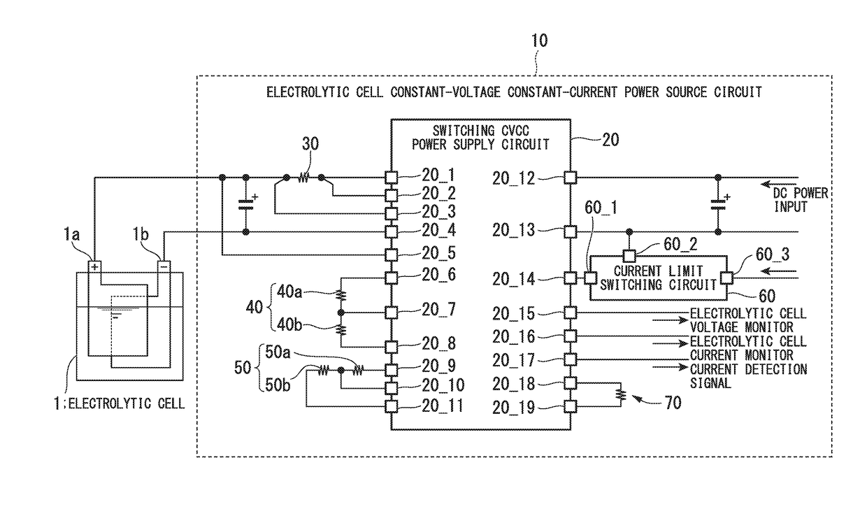
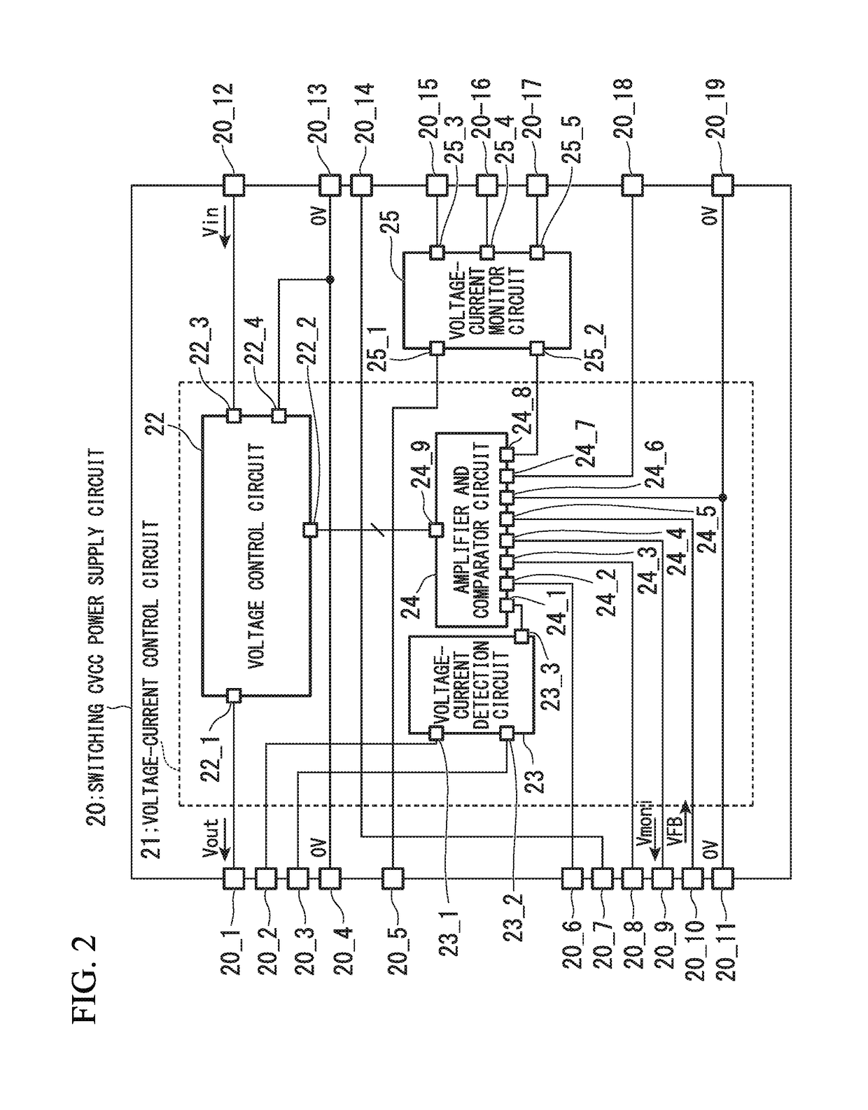
[0075]Next, with reference to FIG. 3 and FIG. 4, is described an operation of the electrolytic cell constant-voltage constant-current power source circuit 10 in which the constant current control mode and the constant voltage control mode are switched according to changes in the concentration of the electrolyte solution in the electrolytic cell 1, to supply an applied voltage to the electrolytic cell 1. FIG. 3 is a diagram for describing controls performed by the electrolytic cell constant-voltage constant-current power source circuit 10. FIG. 4 is an enlarged view of the portion of switching from the constant current control to the constant voltage control shown in FIG. 3. In FIG. 3 and FIG. 4, times on the horizontal axis are different. These figures show the control having been performed under the same conditions on different days and at different times.

[0076]FIG. 3 shows electrolysis in the electrolytic cell 1 that uses the electrolytic cell constant-vol...

second embodiment

Description of Second Embodiment

[0088]In a second embodiment, there is described a constant current control board that prevents temperature rise in an electrolytic cell by performing throttling control of electrolysis according to an environmental temperature, without directly measuring the temperature of the interior and the surface of an electrolytic cell.

[0089]FIG. 5 is a diagram showing a configuration of an incorporated device 100 in which an electrolytic cell and a constant current control board are incorporated therein.

[0090]The electrolytic cell is equivalent to the electrolytic cell 1 described above, and the constant current control board is equivalent to the electrolytic cell constant-voltage constant-current power source circuit 10 in the above description (power control device). The incorporated device 100 is a device that uses electrolysis water produced in the electrolytic cell 1, and has the electrolytic cell 1 and the electrolytic cell constant-voltage constant-curr...

example of experiment

[0096]Here is described an example of an experiment in which the throttling control was performed, using the electrolytic cell 1, the electrolytic cell constant-voltage constant-current power source circuit 10, and the constant temperature reservoir (incorporated device 100) having these incorporated therein, with reference to FIG. 6 through FIG. 14. FIG. 6 through FIG. 12 respectively show changes in the electric current value observed over time at respective rated temperatures, where the rated temperatures are 30° C. to 50° C.

[0097]As the electrolytic cell 1, an electrolytic cell with six cells was used. An adjustment was made by supplying 9% hydrochloric acid in the electrolytic cell 1, so that the electrolysis voltage at the time of applying a 3A electrolysis current to the switching CVCC power supply circuit 20 would be 10V. Chlorine gas produced as a result of the electrolysis was injected to water of a flow rate 20 L per hour.

[0098]FIG. 6 is a diagram showing changes in the e...


PUM

PropertyMeasurementUnit
Temperatureaaaaaaaaaa
Currentaaaaaaaaaa

Abstract

Provided is an incorporated device that incorporates therein an electrolytic cell and a power control device that is capable of suppressing temperature rise in the electrolytic cell to thereby suppress a reduction in the life of electrodes, and a method for controlling an incorporated device. The incorporated device incorporates therein an electrolytic cell and a power control device that is capable of suppressing temperature rise in the electrolytic cell to thereby suppress a reduction in the life of electrodes. The power control device includes: a voltage-current control circuit that supplies, in a constant current control mode, an electrolysis current to the electrolytic cell while the voltage-current control circuit controls the electrolysis current not to exceed a current value of a reference current, the current value of the reference current being preliminary set according to a rated current of a unit cell constituting the electrolytic cell; and a temperature detecting part that detects an environmental temperature of an outside of the electrolytic cell, the environmental temperature being a temperature of an inside of the incorporated device. The voltage-current control circuit stops supply of the electrolysis current when a detected temperature of the temperature detecting part falls outside of a preliminarily set rated temperature range, and resumes supply of the electrolysis current when the detected temperature of the temperature detecting part returns within the rated temperature range.

Description

TECHNICAL FIELD[0001]The present invention relates to an incorporated device in which an electrolytic cell for producing, by performing electrolysis on a raw material solution, electrolysis water to be used for sterilized water and the like, and a power control device that supplies electric power to this electrolytic cell are incorporated, and to a method for controlling an incorporated device. Priority is claimed on Japanese Patent Application No. 2014-228806, filed Nov. 11, 2014, the contents of which are incorporated herein by reference.BACKGROUND ART[0002]Heretofore, electrolytic cells and power control devices have been available on the market as stand-alone devices (electrolysis modules). However, attention is being drawn to incorporating these into an existing device or system, for example, a device (an incorporated device) that requires sterilized water such as a washing machine, an air conditioner, a dish washer, and a nursing-purposed modular bath.[0003]In the case of elec...

Claims


Application Information

Patent Timeline
IPC IPC(8): H01M8/0432H01M8/04537H01M8/18C25B15/02C25B1/04C25C1/00H01M8/00
CPCH01M8/04365C25B1/04C25B15/02H01M8/00H01M8/18C25C1/00H01M8/04567C02F1/46Y02E60/36Y02E60/50C25B9/65C02F1/46104C02F2201/4614C02F2201/46135
Inventor MATSUYAMA, KOKI
Owner MORINAGA MILK IND CO LTD
Learn More