Autofocus system for a high speed periodically modulated variable focal length lens

a technology of variable focal length and autofocus system, which is applied in the field of precision metrology, can solve the problems that the known methods are not ideally suited to take advantage of the characteristics of high speed periodic modulated vfl lens, and achieve the effect of high focusing ra

Active Publication Date: 2017-11-09
MITUTOYO CORP
View PDF0 Cites 27 Cited by
  • Summary
  • Abstract
  • Description
  • Claims
  • Application Information

AI Technical Summary

Benefits of technology

[0007]As outlined above, generally speaking, the known methods of autofocusing an imaging system including a high speed periodically modulated VFL lens at a particular workpiece surface, in order to image that particular surface and / or establish its particular Z-height, are slower than desired. Known methods are not ideally suited to take advantage of the characteristics of a high speed periodically modulated VFL lens, and in particular are a limiting factor in relation to the extremely high focusing rate that may potentially be provided when using a TAG lens.

Problems solved by technology

Known methods are not ideally suited to take advantage of the characteristics of a high speed periodically modulated VFL lens, and in particular are a limiting factor in relation to the extremely high focusing rate that may potentially be provided when using a TAG lens.

Method used


Image

  • Autofocus system for a high speed periodically modulated variable focal length lens
  • Autofocus system for a high speed periodically modulated variable focal length lens
  • Autofocus system for a high speed periodically modulated variable focal length lens

Examples


Embodiment Construction

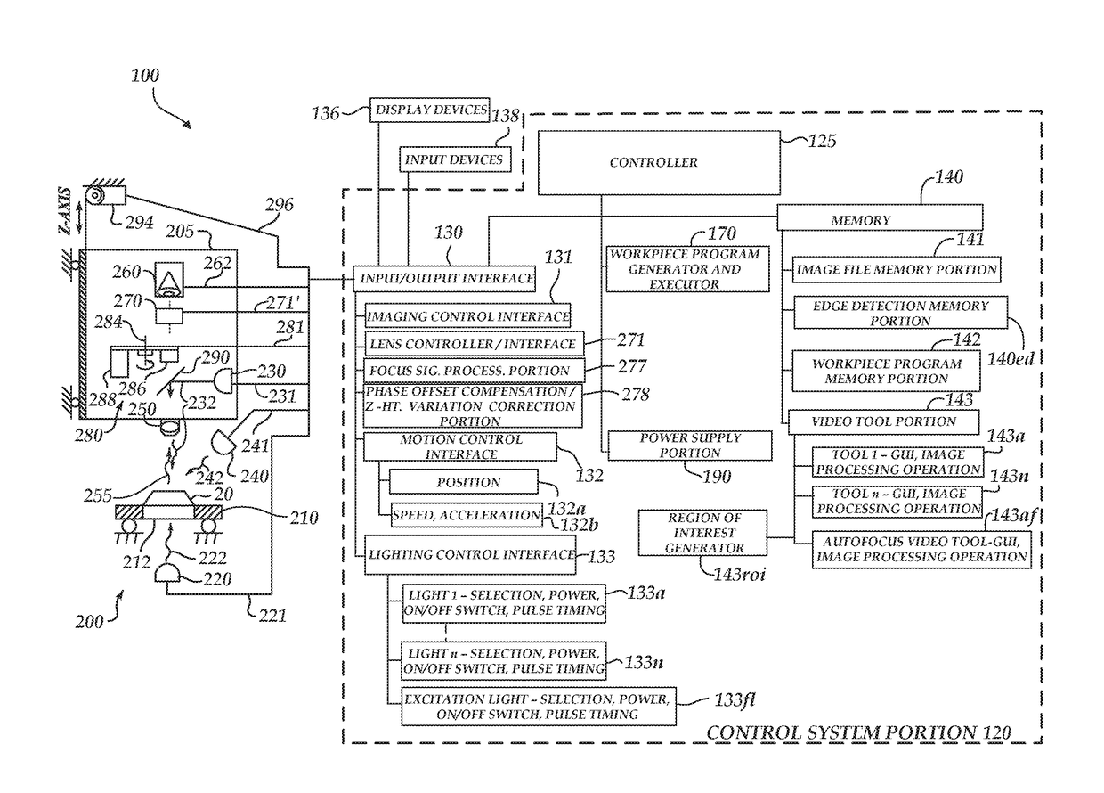
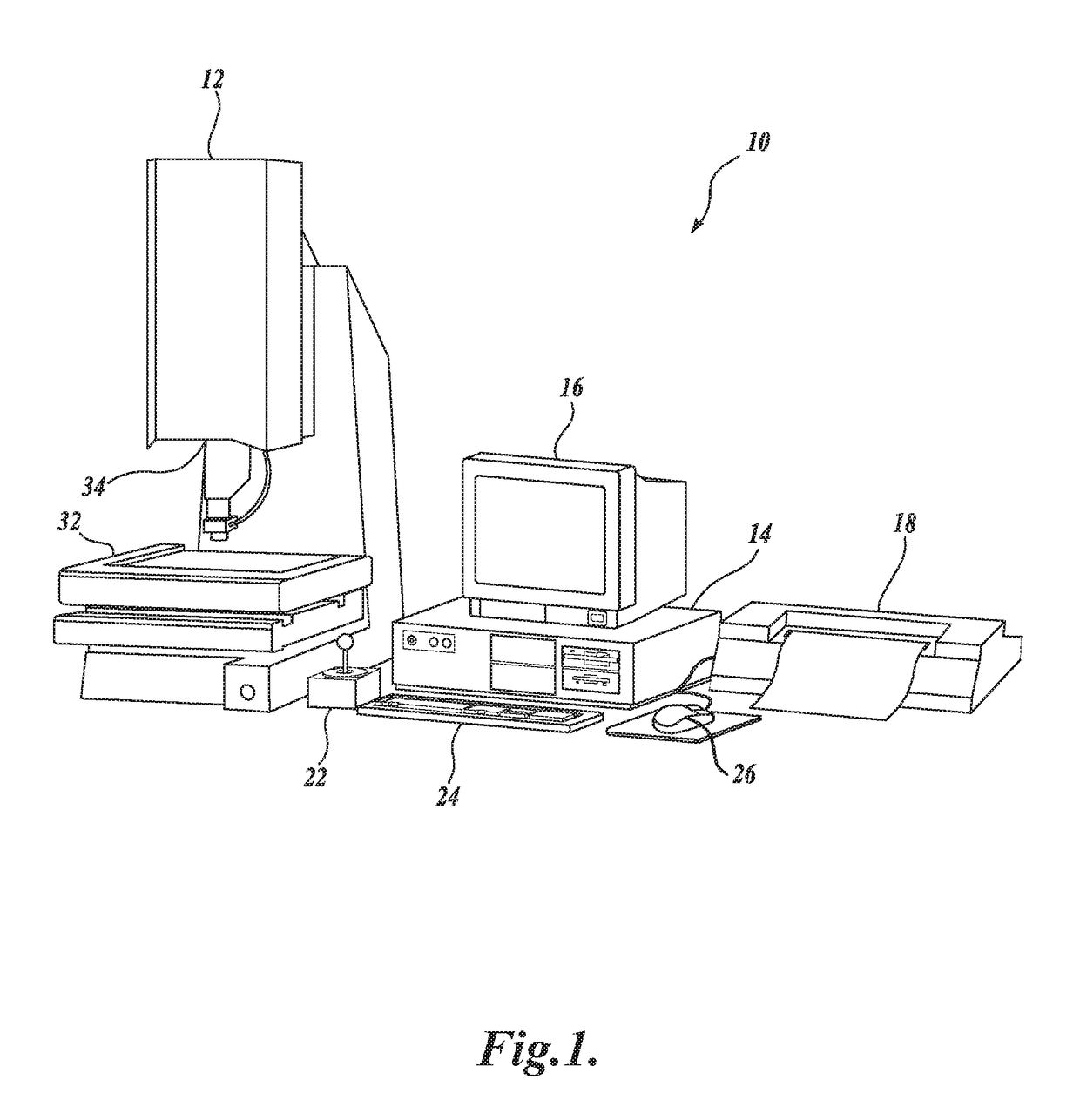
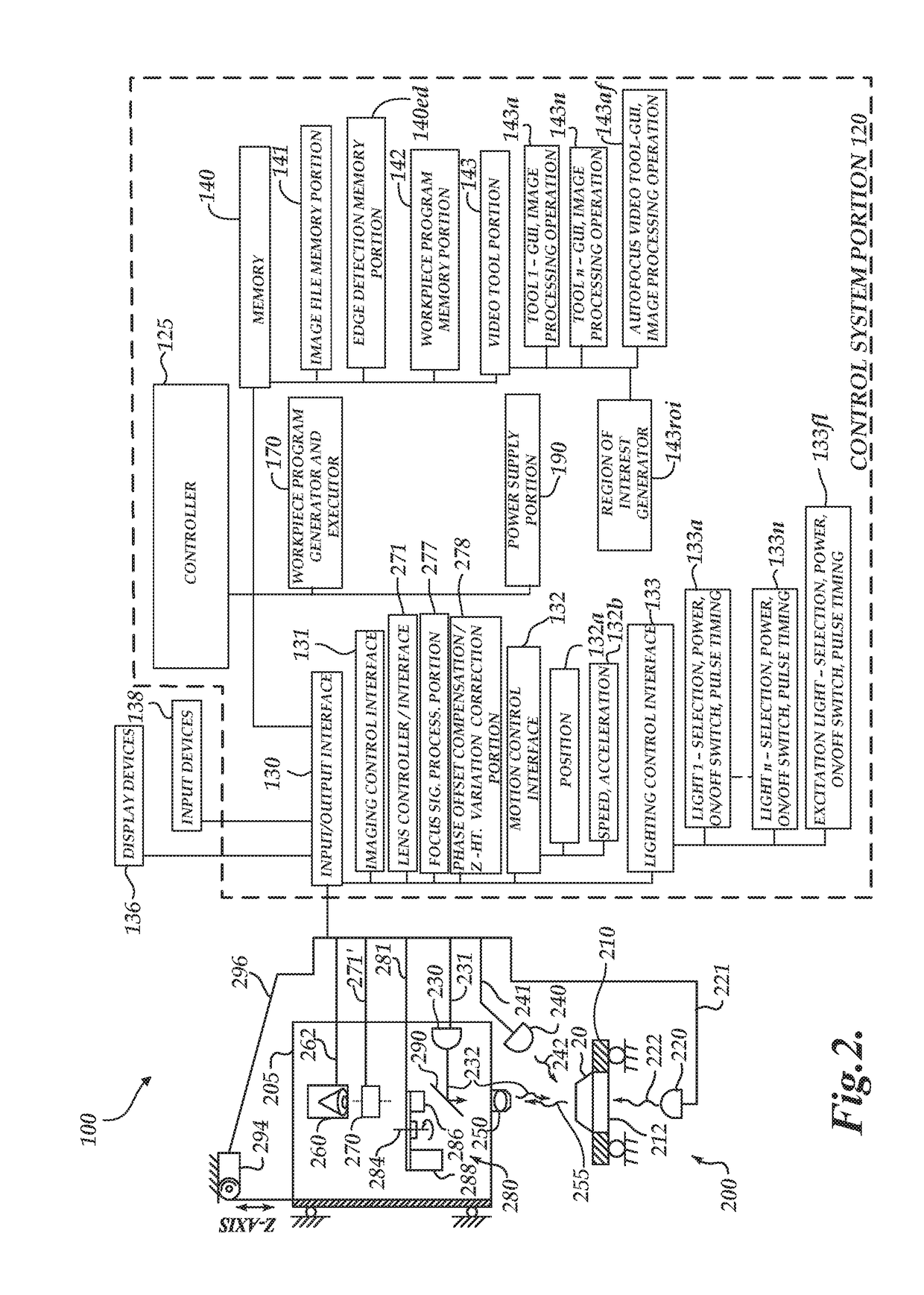
[0026]FIG. 1 is a block diagram of one exemplary machine vision inspection system 10 usable in accordance with principles disclosed herein. The machine vision inspection system 10 includes a vision measuring machine 12 that is operably connected to exchange data and control signals with a controlling computer system 14, and with a monitor or display 16, printer 18, joystick 22, keyboard 24, and mouse 26. The monitor or display 16 may display a user interface suitable for controlling and / or programming the machine vision inspection system 10. In various implementations, a touchscreen tablet or the like may be substituted for and / or redundantly provide the functions of any or all of the computer system 14, display 16, joystick 22, keyboard 24, and mouse 26.

[0027]More generally, the controlling computer system 14 may comprise or consist of any computing system or device, and / or distributed computing environment, and the like, any of which may include one or more processors that execute...


PUM


Abstract

A system for providing an automatically focused image comprises an imaging system including a high speed periodically modulated variable focal length (VFL) lens, a VFL lens controller, a VFL-projected light source, a focus determining portion, an exposure timing adjustment circuit, and an exposure strobe time controller. The focus determining portion comprises an optical detector that inputs reflected VFL-projected light that is projected to, and reflected from, a workpiece through the VFL lens, and provides a focus deviation signal. The exposure timing adjustment circuit provides an exposure timing adjustment signal based on the focus deviation signal, which indicates a time when the imaging system focus Z-height approximately coincides with the workpiece surface Z height. The exposure strobe time controller uses the exposure timing adjustment signal to adjust the image exposure time so the imaging system focus Z-height coincides with the workpiece surface Z height at the adjusted image exposure time.

Description

CROSS-REFERENCE TO RELATED APPLICATION(S)[0001]This application is a continuation-in-part of U.S. patent application Ser. No. 15 / 145,682, entitled “PHASE DIFFERENCE CALIBRATION IN A VARIABLE FOCAL LENGTH LENS SYSTEM,” filed on May 3, 2016, the disclosure of which is hereby incorporated herein by reference in its entirety.BACKGROUNDTechnical Field[0002]This disclosure relates to precision metrology and, more particularly, to machine vision inspection systems and other optical systems in which a variable focal length lens may be utilized to periodically modulate a focus position.Description of the Related Art[0003]Precision machine vision inspection systems (or “vision systems” for short) may be used for precise measurements of objects and to inspect other object characteristics. Such systems may include a computer, camera, optical system, and a stage that moves to allow workpiece traversal. One exemplary system, characterized as a general-purpose “off-line” precision vision system, i...

Claims


Application Information

Patent Timeline
Patent Type & Authority Applications(United States)
IPC IPC(8): H04N5/232H04N5/225G06T7/00H04N5/235
CPCH04N5/23212H04N5/2256H04N5/2254G06T2207/30164H04N5/23216G06T7/0004H04N5/2353G02B7/282G03B13/36H04N23/55H04N23/67G01N21/8806G01N2021/8838H04N23/56H04N23/73H04N23/62
Inventor BRYLL, ROBERT KAMILDELANEY, MARK LAWRENCE
Owner MITUTOYO CORP
Why Eureka
Try Eureka