Apparatus and method for filling containers

a container and apparatus technology, applied in the field of apparatus and a container filling method, can solve the problems of difficulty in performing format change, maintenance or machine part adjustment operations, considerable wastage of operating fluid, etc., and achieve the effect of reducing the time needed for performing sterilisation operations, restoring sterility along the line, and being faster and more practical

Active Publication Date: 2017-11-16
GEA PROCOMAC
View PDF0 Cites 2 Cited by
  • Summary
  • Abstract
  • Description
  • Claims
  • Application Information

AI Technical Summary

Benefits of technology

[0029]In particular, an object of the present invention is to provide an apparatus for filling containers wherein the volumes to be sterilised and the time needed for performing the sterilisation operations are further reduced with respect to the known solutions.
[0030]A further object of the present invention is to provide a method for filling containers that is quicker and more practical than the known methods, wherein the downtime due to restoring sterility along the line is further reduced.
[0034]dispensing means for dispensing a fluid into the treatment volume of each neck so that it flows over the neck of the corresponding container in order to prevent the entry of contaminants into the treatment volume.
[0037]Preferably, each filling valve is associated with a sanitisation device of the dummy bottle type which can be configured in at least one rest position wherein it prevents interference with the filling valve and in one active position wherein the dummy bottle is arranged below the filling valve closing the treatment volume so as to prevent fluid communication with the external environment.
[0062]dispensing a flow of fluid into the treatment volume so as to flow over the neck of the container in order to prevent the entry of contaminants into the treatment volume;

Problems solved by technology

The main disadvantage of the cleanroom is therefore represented by its substantial volume, therefore lengthy and expensive sterilisation procedures are required.
There is also considerable wastage of operating fluids, for example sanitisation liquids and sterile air, and wear phenomena, for example, of the filters needed to purify the air adapted to generate overpressure within the cleanroom so as to prevent the entry of contaminants from the external environment.
A further disadvantage of the use of a cleanroom regards the difficulty in performing format change, maintenance or machine part adjustment operations, due to the risk of contamination that such operations imply.
Access to the cleanroom by an operator is therefore also particularly critical.
The main drawback of this solution clearly lies in the substantial structural complexity, the still considerable dimensions of the sterile zones (even if they are restricted and shaped around the operating units) and the difficulty to maintain sterile conditions within the isolators.
Furthermore, not all the manual procedures required during operation (e.g. removal of obstacles) can be performed with the use of handling gloves: in some cases, it may still be necessary to open the isolator access door, resulting in the loss of sterile conditions.
Upon completion of the procedure, a sterile environment must be restored, resulting in an evident loss of time due to downtime of the line.
Still from this point of view, the format change operations are also long and not very practical.
However, this solution, known in the sector as a “neck-ring isolator” requires the provision of a further confinement of the body-zones of containers in order to prevent dispersions of the sterilising agents into the environment external to the toroidal isolator, with consequent risks to the health of the operators.
Therefore, even moving over to “neck-ring isolator” architecture, the problems of maintaining and / or restoring sterility remain.

Method used


Image

  • Apparatus and method for filling containers
  • Apparatus and method for filling containers
  • Apparatus and method for filling containers

Examples


Embodiment Construction

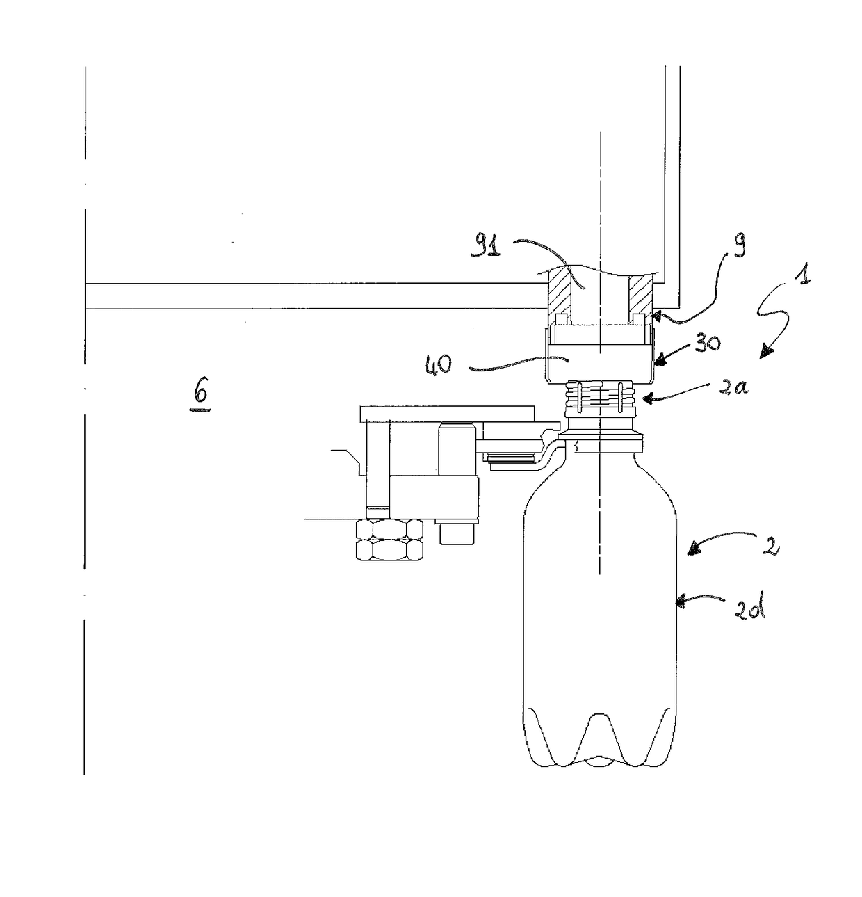
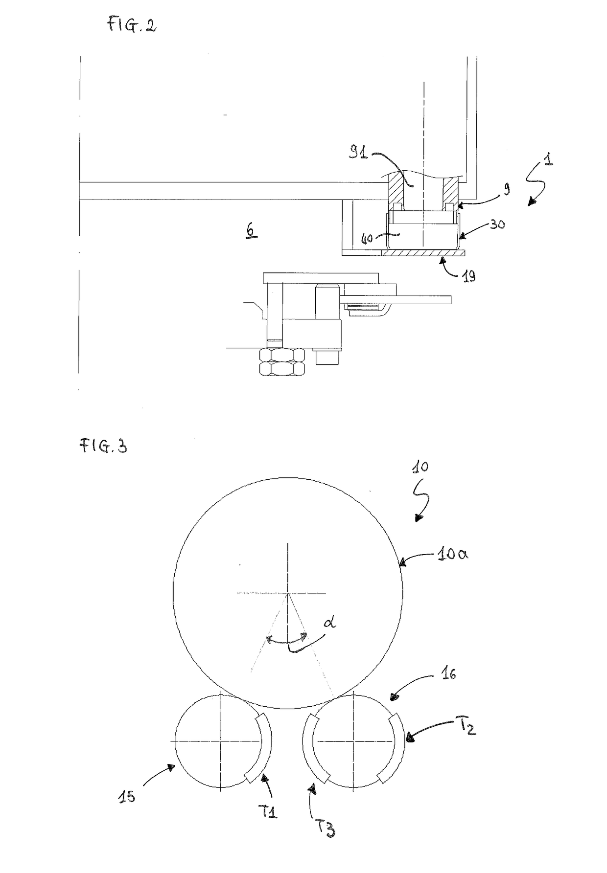
[0081]With reference to the figures, 10 indicates an apparatus for filling containers 2 with a filling product, for example with a drink.

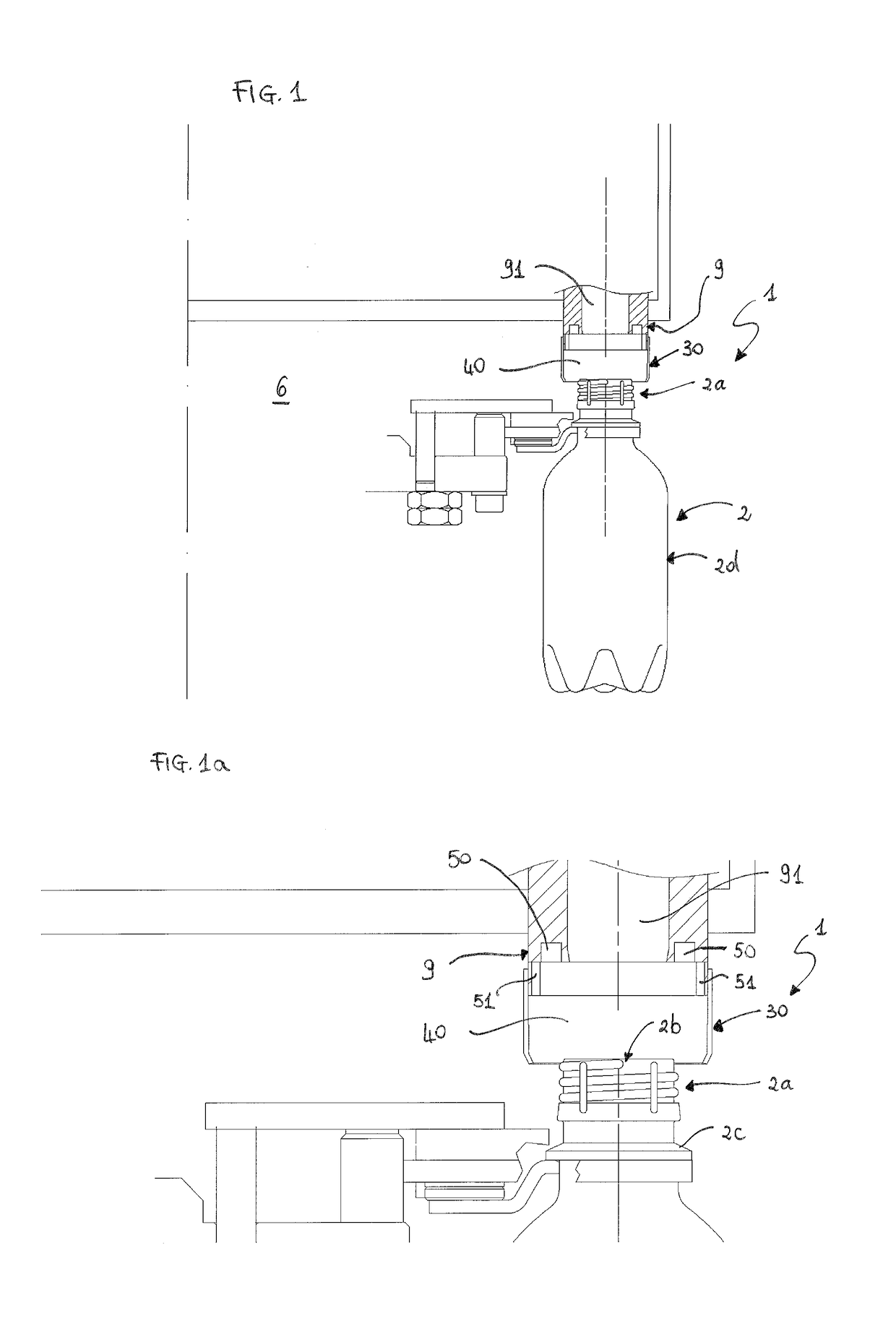
[0082]The filling apparatus 10 comprises a rotating carousel 10a with a plurality of filling stations 1 in each of which a filling valve 9 is arranged below which the corresponding container 2 can be positioned with its mouth 2b facing towards the filling valve 9.

[0083]Originally, the filling apparatus 10 comprises means for separating 30 a treatment volume 40 of the individual neck 2a of each container 2 from an external environment 6 containing the body 2d of the container 2. In particular, the treatment volume 40 is comprised between the corresponding filling valve 9 and at least a part of the neck 2a of the container 2. The treatment volume 40 therefore also protects the internal surface of the container 2 which comes into contact with the filling product. The filling apparatus 10 further comprises dispensing means for dispensing a fluid into t...


PUM

PropertyMeasurementUnit
volumeaaaaaaaaaa
volumesaaaaaaaaaa
dead angleaaaaaaaaaa

Abstract

A method for filling a container (2) with a filling product, comprising the steps of: positioning the container (2) in a filling station (1) so that its mouth (2b) is below the filling valve (9); separating a treatment volume (40) of the neck (2a) comprised between the filling valve (9) and at least one part of the neck (2a) of the container (2) from an external environment (6) containing the body (2d) of the container (2); dispensing plasma into the treatment volume (40) so that it flows over the neck (2a) of the container (2); enabling the filling valve (9) to dispense the filling product into the container (2).

Description

TECHNICAL FIELD[0001]The present invention relates to an apparatus and a method for filling containers.[0002]The reference sector is the bottling of so-called “sensitive” food products, i.e. products that are particularly sensitive to bacteriological contamination and oxidation, such as, for example, isotonic drinks, juices, nectars, soft drinks, tea, milk-based drinks, coffee-based drinks, etc., for which the prevention of possible microbiological contamination throughout all packaging stages is of fundamental importance.BACKGROUND ART[0003]Packaging lines using aseptic technology are already known, wherein the various operations take place in a controlled contamination environment, so that the bottled products can be stored for a prolonged period of time and have chemical / physical and organoleptic stability even at room temperature.[0004]In the first installations containers were produced in non-aseptic apparatuses and subsequently the moulded containers were transferred into a cl...

Claims


Application Information

Patent Timeline
Patent Type & Authority Applications(United States)
IPC IPC(8): B67C7/00A61L2/26A61L2/14B67C3/28B67C3/26B67C3/22
CPCB67C7/0086B67C7/004B67C3/28B67C3/26A61L2/14A61L2/26B67C2003/228B67C2003/2688A61L2202/23B67B2201/10B67C7/0073B67C2003/2697
Inventor PAGLIARINI, PAOLO
Owner GEA PROCOMAC
Why Eureka
Try Eureka