
Turbocharger

a turbocharger and turbocharger technology, applied in the direction of liquid fuel engines, machines/engines, electric apparatus casings/cabinets/drawers, etc., can solve the problems of comparatively large thermal load applied to the intercooler, disadvantage, and heat quantity, and achieve the effect of improving the boost pressure and maintaining stably

Inactive Publication Date: 2017-11-16
MAHLE FILTER SYST JAPAN CORP
View PDF12 Cites 19 Cited by
  • Summary
  • Abstract
  • Description
  • Claims
  • Application Information

AI Technical Summary

Benefits of technology

The invention is about a cooling system for a turbocharger. The system includes an electric motor and two compressor wheels. The motor is placed between the two compressor wheels, and there are separate cooling parts for the air in the compressor passages and for the motor stator and control unit. This reduces the likelihood of heat affecting the air before it reaches the second-stage compressor wheel and the motor. By combining the cooling parts, the performance of both the boost pressure and motor-stator cooling are improved. This eliminates the need for an external cooler or heat exchanger, making it more space-efficient. The technical effects of the invention are reduced thermal impact on the air and improved cooling performance, along with space-saving benefits.

Problems solved by technology

The quantity of heat, which is delivered to the first compressor stage, is an disadvantage in rising a boost pressure at the first compressor stage and also in rising a boost pressure at the second compressor stage subsequently to the first compressor stage.
Thus, the redundant flow passage system including the second flow passage as well as the first flow passage leads to a pressure loss.
Also, the air discharged from the pressure side of the first compressor stage has more of the quantity of heat removed from the motor stator, and thus a comparatively large thermal load is applied to the intercooler.
Therefore, the prior-art turbocharger system requires a comparatively large capacity of intercooler.
Necessarily, the entire system configuration of the turbocharger including the intercooler has to be undesirably increased in size.

Method used


Image

  • Turbocharger
  • Turbocharger
  • Turbocharger

Examples


Embodiment Construction

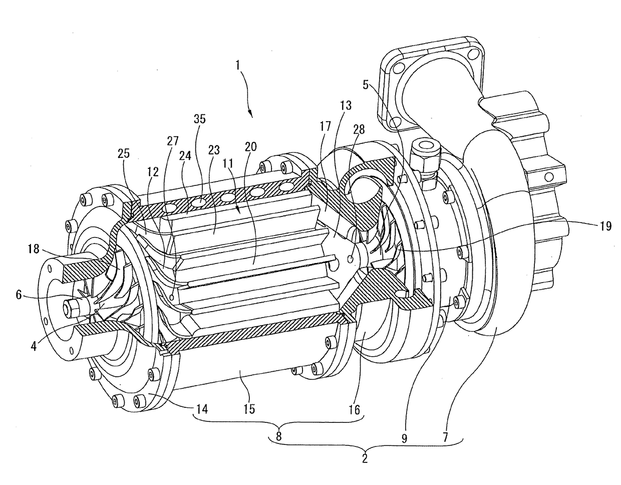
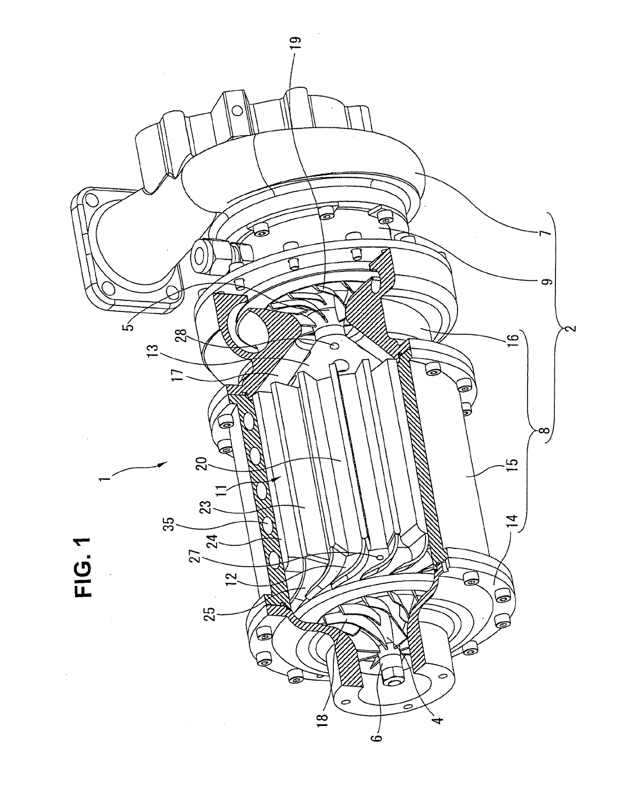
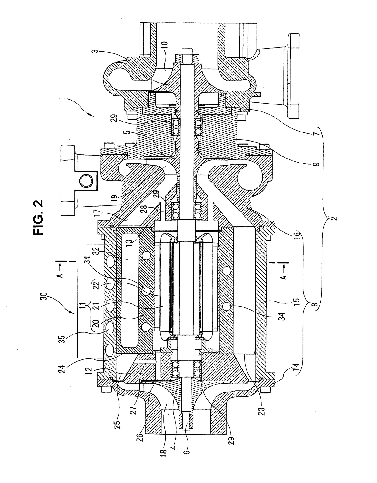
[0025]The detailed description of embodiments of a turbocharger according to the invention will be given with reference to the accompanying drawings. FIG. 1 is a partially cutaway view in perspective of a turbocharger 1 of the embodiment. FIG. 2 is a longitudinal cross-sectional view of the turbocharger 1 of the embodiment shown in FIG. 1. FIG. 3 is a lateral cross-sectional view taken along the line A-A of FIG. 2. FIG. 4 is a schematic perspective view illustrating the water cooling system of the turbocharger 1 shown in FIGS. 1-3. FIG. 5 is a left-hand side view illustrating the water cooling system shown in FIG. 4.

[0026]Referring now to FIGS. 1-2, turbocharger 1 is a two-stage supercharging turbocharger in which air to be fed into an intake system of an internal combustion engine (not shown) mounted on a vehicle can be compressed or supercharged within a turbocharger housing 2 in two stages. That is to say, turbocharger 1 is configured such that a rightmost-end turbine wheel 3, a ...


PUM


Abstract

In a two-stage supercharging electric-assist turbocharger, a first compressor wheel, a rotor of an electric motor, a second compressor wheel, and a turbine wheel are coaxially coupled to a same, common shaft member, in that order. A compressor housing is structured to define therein a communicating passage to accommodate the electric motor in the communicating passage. A first water jacket is formed in at least one rib integrally formed with an outer periphery of a motor housing and also serving as a radiating fin, for forced-cooling air flowing through the communicating passage. A second water jacket is formed in a motor housing for forced-cooling a stator of the electric motor. A third water jacket is formed in an intermediate housing constructing a part of the compressor housing for forced-cooling a control unit configured to control the electric motor.

Description

TECHNICAL FIELD[0001]The present invention relates to a turbocharger for an internal combustion engine, and specifically to a two-stage supercharging turbocharger having an electric-assist function by means of an electric motor.BACKGROUND ART[0002]One such two-stage supercharging electric-assist turbocharger has been disclosed in the following Patent document 1.[0003]In the turbocharger disclosed in the Patent document 1, a two-stage supercharging compressor section is constructed by a first compressor stage and a second compressor stage arranged adjacent to each other. An electric motor is arranged on the side of the first compressor stage, whereas an exhaust-gas turbine section is arranged on the side of the second compressor stage, in a manner so as to sandwich the first and second compressor stages between the electric motor and the turbine section. The turbine section is driven by exhaust gas energy. The first compressor wheel, the second compressor wheel, the motor rotor, and ...

Claims


Application Information

Patent Timeline
Patent Type & Authority Applications(United States)
IPC IPC(8): F02B37/04F04D29/28F01P7/14F01P3/20F02B37/14F04D17/12F04D29/58F04D27/00
CPCF02B37/04F02B37/14F04D17/12F04D27/004F04D29/284F04D29/584F01P3/20F01P7/14F01P2060/12F02B29/0462F02B29/0475F02B37/10H02K9/19H05K7/20218F02B37/013F02B33/34F02B39/005F02B39/10H02K5/04H02K11/33F04D25/024F04D25/0606F04D29/5806Y02T10/12F04D29/5813H05K5/00
Inventor YAMASHITA, TAKAHISASIVARAMAN, VIJAYAKUMARIWANO, HARUO
Owner MAHLE FILTER SYST JAPAN CORP
Learn More