Universal Joint

a universal joint and joint technology, applied in the field of universal joints, can solve the problems of affecting the operation life of the drill string including the universal joint, affecting the operation of the drill string, and affecting the operation life of the drill string components, so as to shorten the drill string, reduce the effect of moving parts and limited movemen

Inactive Publication Date: 2017-11-16
ULTERRA DRILLING TECH LP
View PDF0 Cites 11 Cited by
  • Summary
  • Abstract
  • Description
  • Claims
  • Application Information

AI Technical Summary

Benefits of technology

[0010]In one other aspect of the invention, an upper member and a lower member are joined by a serpentine retainer that engages circumferential teeth on both members to maintain rotational relation of the connected members. With the assembly under torque, the lower member rotates with the upper member to transmit torque. The retainer provides limited movement between the members to accommodate axial, angular and / or lateral misalignment between shafts. The serpentine retainer can also flex to allow limited rotation of the upper member in relation to the lower member. The serpentine retainer or connector element joining the toothed members provides a compact assembly allowing the components of the drill string to be positioned close together shortening the drill string. The joint has limited moving parts, few components and is inexpensive to manufacture.

Problems solved by technology

The components of the drill string including the universal joint are subjected to extreme torque forces, elevated operating temperatures and abrasive drilling fluids, all of which can have an adverse effect on the operational life of drill string components.
Constant relative movement of the components of a universal joint during operations, together with abrasive drilling mud, causes abrasion and erosion of mating components.
Due to the constant relative movement of the components and aggressive downhole environment, they do not readily lend themselves to conventional sealing arrangements.
Operational failure of the joint or its components requires removal of the drill string from the borehole and downtime for the operation which increases operational expenses substantially.

Method used


Image

  • Universal Joint
  • Universal Joint
  • Universal Joint

Examples


Embodiment Construction

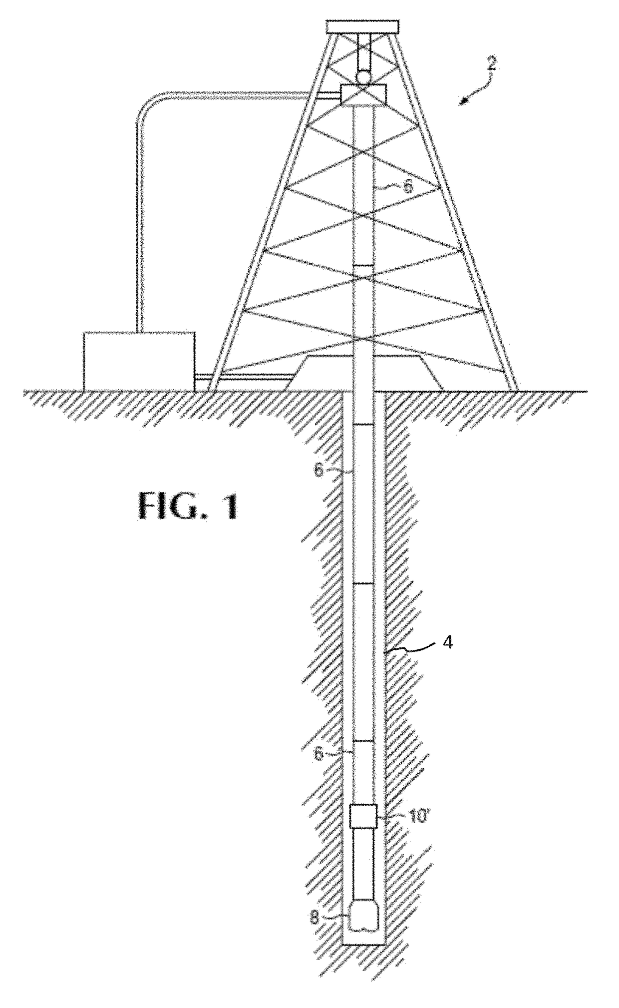
[0024]A drill string in its basic form consists of sections of threaded pipe and tools assembled end to end with a drill bit at a distal end for advancing a borehole. The drill string can be miles long and rotated at a proximal end of the pipe by a drilling rig to turn the drill bit and advance the borehole. Many different components can be assembled to the drill string to perform a range of functions such as reaming out obstructions from the borehole, widening the borehole or vibrating the drill string to mitigate friction between the string and the borehole.

[0025]Positive displacement or mud motors can be installed at the distal end of the drill string to drive the drill bit instead of, or in addition to, driving the drill string from the above ground drill rig. Fluid is pumped down the drill string during operation under pressure to flush material out of the borehole. A mud motor uses the pressure of the fluid to drive a rotor in a stator housing. The output of the motor is eccen...


PUM


Abstract

A universal joint assembled in a drill string transfers torque between two components where rotation of the components may not be completely aligned. The universal joint includes upper and lower members with radial teeth connected by a serpentine retainer. As the joint rotates the members can pivot within the confines of the serpentine retainer to accommodate misalignment of the components. Axial force can be transferred through a bearing member between the members.

Description

RELATED APPLICATION[0001]This application claims the benefit of U.S. Provisional Application No. 62 / 334,943, filed May 11, 2016, entitled, “Universal Joint,” which is incorporated herein in its entirety by reference for all purposes.FIELD OF THE INVENTION[0002]This invention relates to universal joints used in downhole drill strings.BACKGROUND[0003]Universal joints are used in mechanical applications to transmit torque between components where there can be misalignment of rotating parts. In a drilling operation, a drill bit is mounted to the end of a drill string. The drill string is rotated from the top of the string or by a motor at the bottom of the string, or both, to rotate the drill bit and advance the borehole. Universal joints can be included in the drill string to accommodate rotational eccentricity. The eccentric rotation is converted into axial rotation in order for the drill bit to advance the borehole efficiently. Eccentricity can be initiated by a motor in the drive as...

Claims


Application Information

Patent Timeline
Patent Type & Authority Applications(United States)
IPC IPC(8): F16D3/52E21B7/04E21B17/05F16D3/72
CPCF16D3/52E21B17/05E21B7/04F16D3/72E21B4/003E21B17/04E21B17/046F16D3/56
Inventor MAW, JASONST. PIERRE, BEAU J.
Owner ULTERRA DRILLING TECH LP
Why Eureka
Try Eureka