Rotary Heat Exchanger Device

a heat exchanger and rotary technology, applied in lighting and heating apparatus, ventilation systems, heating types, etc., can solve the problems of high assembly cost and coupling no longer working reliably, and achieve the effects of saving complicated calibration, reducing pressure loss, and high heat recovery

Inactive Publication Date: 2017-11-16
TBM
View PDF5 Cites 37 Cited by
  • Summary
  • Abstract
  • Description
  • Claims
  • Application Information

AI Technical Summary

Benefits of technology

[0005]Embodiments of the present invention provide an enhanced rotary heat exchanger device, which in particular requires a reduced assembly cost and has increased reliability.
[0011]Such a rotary heat exchanger device also in particular involves the advantage that no coupling means which are liable to wear, such as drive belts or gear-wheels or other means for producing a form-fit or friction coupling between the rotor and the rotary heat exchanger are required. It saves complicated calibration and readjustment of the coupling means and / or drive motor.
[0012]The fact that the drive motor is no longer arranged adjacent to the outer wall of the rotary heat exchanger enables that, for a unchanged size of a housing of the rotary heat exchanger device, the diameter thereof can be enlarged, which results in a higher heat recovery and a lower pressure loss with the same air performance.

Problems solved by technology

The coupling between the outer wall of the rotary heat exchanger and rotor by means of a form-fit and / or friction coupling requires a high level of positional accuracy of the drive motor and rotary heat exchanger in relation to each other, and therefore high assembly costs.
There is also a risk that, even at low abrasion, the coupling no longer functions reliably.

Method used


Image

  • Rotary Heat Exchanger Device
  • Rotary Heat Exchanger Device
  • Rotary Heat Exchanger Device

Examples


Embodiment Construction

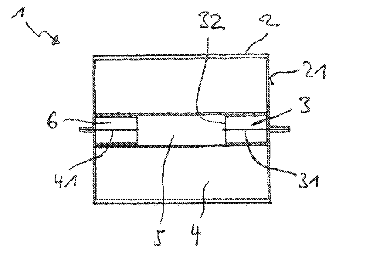
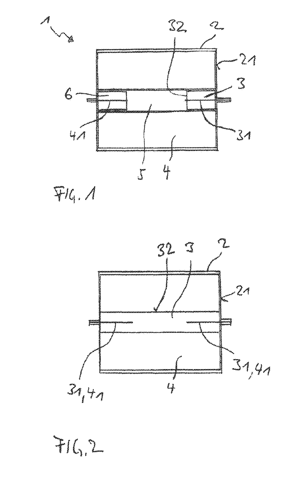
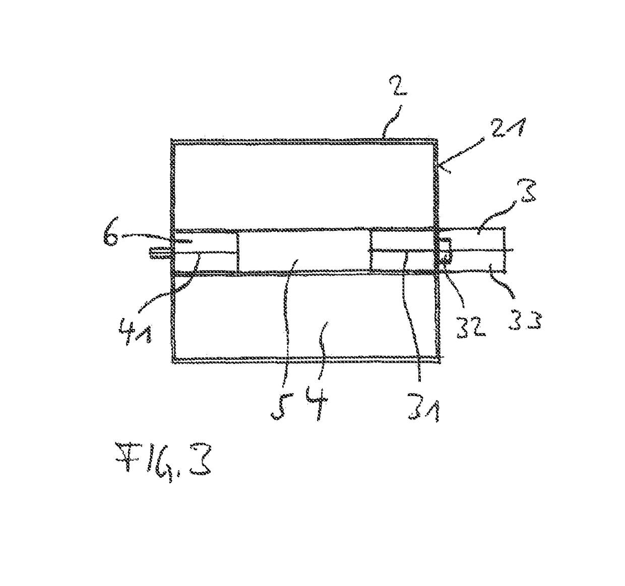
[0018]The FIGS. 1 to 3 show in each case one exemplary embodiment of a rotary heat exchanger device 1 having, for example, a cubic housing 2, for example, made of sheet metal or plastic, an electric drive motor 3 and a cylindrical rotary heat exchanger 4. The housing 2 comprises openings (not shown) at the sides for air intake into and air outlet out of the rotary heat exchanger 4.

[0019]In the exemplary embodiments in accordance with FIGS. 1 and 2, the drive motor 3 is arranged within the rotary heat exchanger 4 in such a way that the axis of rotation of the rotor 32 of the drive motor 3, i.e., the motor axis of rotation 31, is coaxial with an axis of rotation of the rotary heat exchanger 4, hereafter heat exchanger axis of rotation 41.

[0020]The rotor 32 is rigidly connected to the rotary heat exchanger 4, for example, by means of a toothing system or a screw fitting between rotary heat exchanger 4 and rotor 32.

[0021]A stator (not shown) of the drive motor 3 is rigidly connected to ...


PUM


Abstract

A rotary heat exchanger device is disclosed. In an embodiment the rotary heat exchanger includes a rotary heat exchanger having a rotary heat exchanger axis of rotation, a drive motor having a stator and a rotor including a rotor axis of rotation and a housing into which the rotary heat exchanger is installed and in which the latter rotates, wherein the rotor axis of rotation and the heat exchanger axis of rotation extend coaxially and the rotor is rigidly connected to the rotary heat exchanger.

Description

[0001]This patent application is a national phase filing under section 371 of PCT / DE2015 / 000537, filed Nov. 11, 2015, which claims the priority of German patent application 20 2014 105 449.9, filed Nov. 12, 2014, each of which is incorporated herein by reference in its entirety.TECHNICAL FIELD[0002]The invention relates to a rotary heat exchanger device, in particular for use in a decentralized ventilation system with heat recovery, comprising a rotary heat exchanger and a drive motor.BACKGROUND[0003]Such a rotary exchanger device is known from DE 20 2009 009 697 U1. In this rotary heat exchanger device the drive motor is an external rotor motor, which is arranged adjacent to the outside wall of the rotary heat exchanger and the rotor thereof drives the rotary heat exchanger directly by means of a direct form-fit and / or friction coupling to the outer wall.[0004]The coupling between the outer wall of the rotary heat exchanger and rotor by means of a form-fit and / or friction coupling ...

Claims


Application Information

Patent Timeline
Patent Type & Authority Applications(United States)
IPC IPC(8): F28D19/04F28F9/013F24F7/00
CPCF28D19/042F28F9/013F24F2203/104F24F7/00F24F12/006F28D11/02F28D19/048H02K7/14F24F2203/1004Y02B30/56
Inventor BRANDMEIER, THOMAS
Owner TBM
Why Eureka
Try Eureka