Winding machine

Active Publication Date: 2017-11-23
GEORG SAHM GMBH & CO KG
View PDF0 Cites 2 Cited by
  • Summary
  • Abstract
  • Description
  • Claims
  • Application Information

AI Technical Summary

Benefits of technology

[0035]The reference signs contained in the claims are not limiting the extent of the matte

Problems solved by technology

For example, the use of a traversing device necessitates the undesired redirection of the winding good.
If, however (for example according to DE 103 24 179 A1 or according to the product “SAHM 460XE” of the applicant) the entire spindle (possibly also with the assigned transmission and the motor for the drive of the spindle) is moved for the creation of the traversing motion, the drive for cre

Method used


Image

  • Winding machine
  • Winding machine
  • Winding machine

Examples


Example

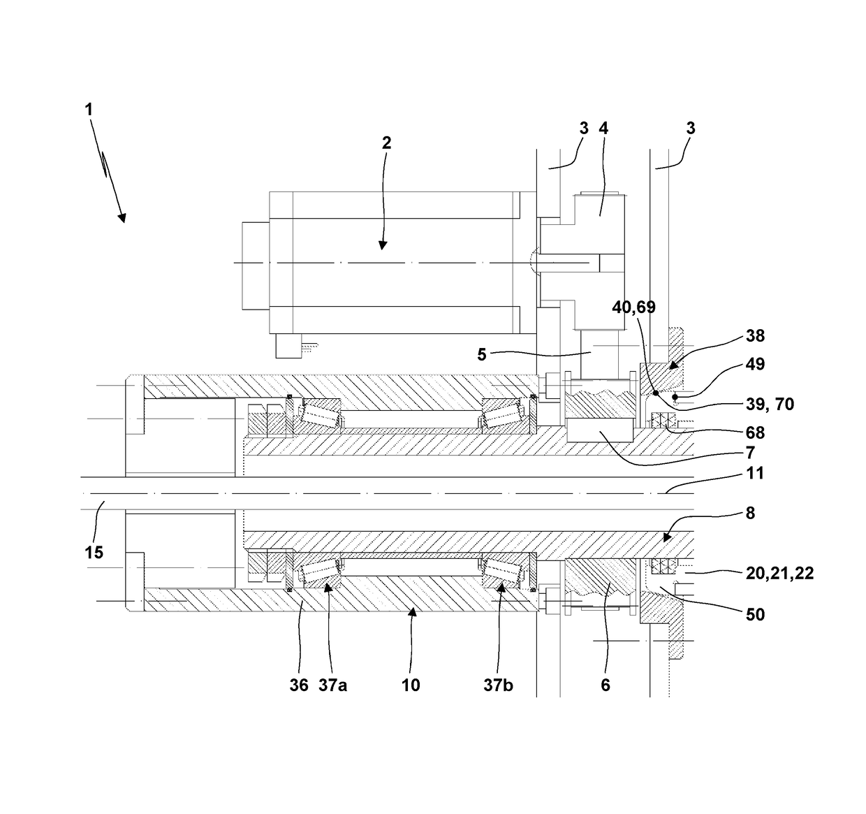
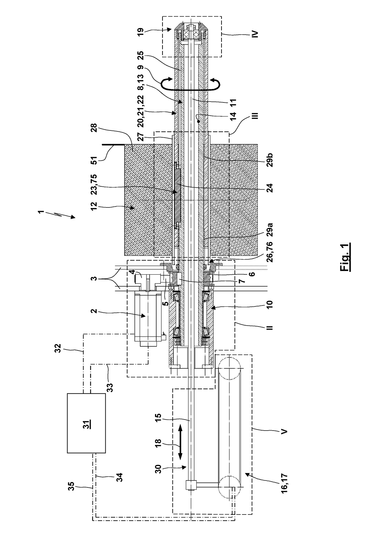
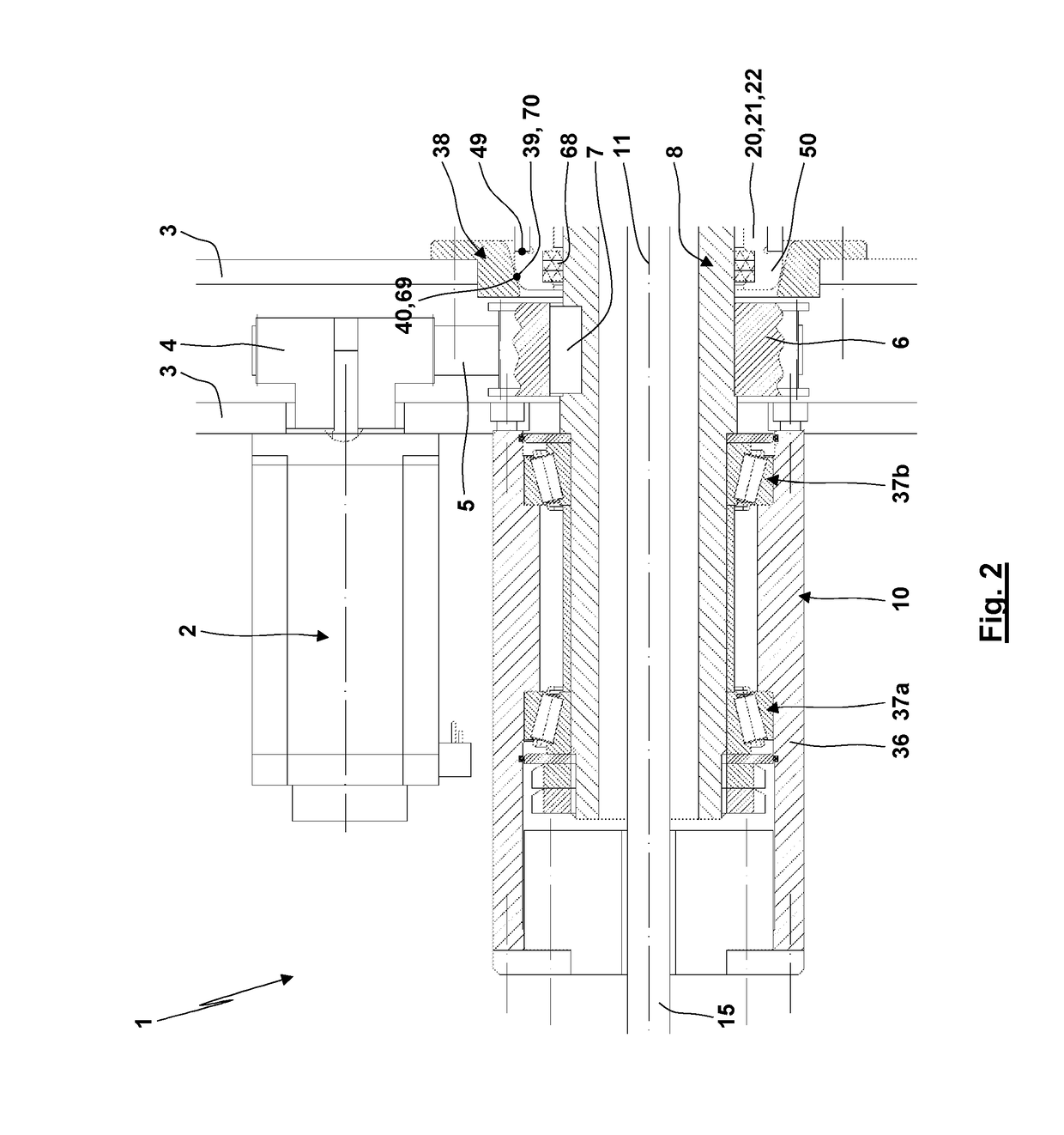
[0044]FIG. 1 shows a winding machine 1. The winding machine 1 has a drive, here an electrical drive 2 which is held on a machine frame 3 of the winding machine 1. A drive wheel 4 driven by the drive 2 is in drive connection with an output-side drive wheel 6 via a traction mechanism 5 such as a toothed belt or a linkage. The output-side drive wheel 6 is rotationally fixedly coupled with a spindle 8, here via a key 7. By actuating the drive 2, with a transmission of gears up or down depending on the transmission ratio between the input-side drive wheel 4 and the output-side drive wheel 6 a rotational motion 9 of the spindle 8 can be induced.

[0045]The spindle 8 via a spindle bearing 10 is supported rotatably around a longitudinal and rotational axis 11 on the machine frame 3. The spindle bearing 10 forms a so-called overhung bearing. The spindle bearing 10 is arranged on one side of the machine frame 3 while the freely extending partial region of the spindle 8 in which the spool 12 is ...


PUM


Abstract

A winding machine (1) for a traversing application of a winding material (51) to a spool sleeve (27) comprises a spindle (8) which is supported for being rotated and for having a fixed axial position. The spindle (8) comprises an inner recess. The winding machine (1) comprises a drive driving the spindle (8) for a rotational movement and a traversing carriage (20). The traversing carriage (20) is supported on the spindle (8) for being movable with a traversing motion (18) in an axial direction relative to the spindle (8). A first coupling element serves for transmitting the rotational movement of the spindle (8) to the traversing carriage (20) and a second coupling element serves for transmitting the traversing motion (18) of the traversing carriage (20) to the spool sleeve (27). The winding machine (1) also comprises an actuation mechanism (30) executing the traversing motion (18). The actuation mechanism (30) is coupled to the traversing carriage (20) for transmitting the traversing motion (18) from the actuation mechanism (30) to the traversing carriage (20). The actuation mechanism (30) extends through the inner recess of the spindle (8).

Description

CROSS REFERENCE TO RELATED APPLICATIONS[0001]This application is a continuation-in-part (CIP) of international application PCT / EP2016 / 053365 with an international filing date of Feb. 17, 2016 and claiming priority to co-pending European patent application No. EP 15 158 293.9 entitled “Spulmaschine”, filed on Mar. 9, 2015.FIELD OF THE INVENTION[0002]The present invention relates to a winding machine for winding a winding good into a spool. Preferably, the winding good to be wound is a winding good which is sensitive to redirection and to cross forces induced by redirection. For example, cross forces due to redirections can lead to damages of edges of the winding good, deformations of the winding good or breaks of possible fibres of the winding good. The winding good especially is a yarn or a thread- or ribbon-shaped winding good. Preferably, the winding good is flexible. The winding good can be a single filament or a multifilament (for example with more than 12,000 single filaments u...

Claims


Application Information

Patent Timeline
IPC IPC(8): B65H54/28H02K7/116
CPCB65H54/2818B65H2701/31H02K7/116B65H54/2803B65H54/543B65H2701/30B65H75/2455B65H54/2821B65H54/2809
Inventor ZAUN, JOCHEN
Owner GEORG SAHM GMBH & CO KG
Why Eureka
Try Eureka