
Hybrid construction machine

a construction machine and hybrid technology, applied in hybrid vehicles, battery/fuel cell control arrangements, electric devices, etc., can solve problems such as inability to properly control motor operation, unstable supply voltage to electric work elements such as motor generators for assistance, and inability to perform control of motor generators and electric motors. the effect of reliability

Active Publication Date: 2017-11-23
SUMITOMO HEAVY IND LTD +1
View PDF45 Cites 9 Cited by
  • Summary
  • Abstract
  • Description
  • Claims
  • Application Information

AI Technical Summary

Benefits of technology

The present invention is a hybrid construction machine that aims to improve reliability by stabilizing the supply voltage to the motor generator and electric work element, and by allowing the electric work element to continue turning even if there is an abnormality in the system. This results in a machine that can still operate efficiently and reliably even if there are unexpected issues with its electric work elements.

Problems solved by technology

For this reason, there is a possibility that a supply voltage to an electric work element, such as a motor generator for assistance, an electric motor for turning, etc., becomes unstable.
When failure occurs in the electric work element, such as a motor generator for assistance, an electric motor for turning, etc., or in a drive control system such as an inverter to drive them, it becomes difficult to appropriately control a motor operation and a generating operation of the motor generator for assistance or a power-running operation and a regenerating operation of the electric motor for turning.
In a worst case, it is possible that controls of the motor generator and the electric motor cannot be performed at all.
Such a problem may arise similarly, when an abnormality occurs in an electric work element other than a motor generator for assistance and an electric motor for turning or in a drive control system such as an inverter to drive such an electric work element.
Moreover, in a conventional hybrid construction equipment, when an abnormality occurs in a drive control system such as a motor generator and an inverter as mentioned above, a normal inverter, in which no abnormality occurs, may be damaged if a large amount of electric power is generated by a generating operation of the motor generator for assistance or a regenerating operation of the electric motor for turning.

Method used


Image

  • Hybrid construction machine
  • Hybrid construction machine
  • Hybrid construction machine

Examples


first embodiment

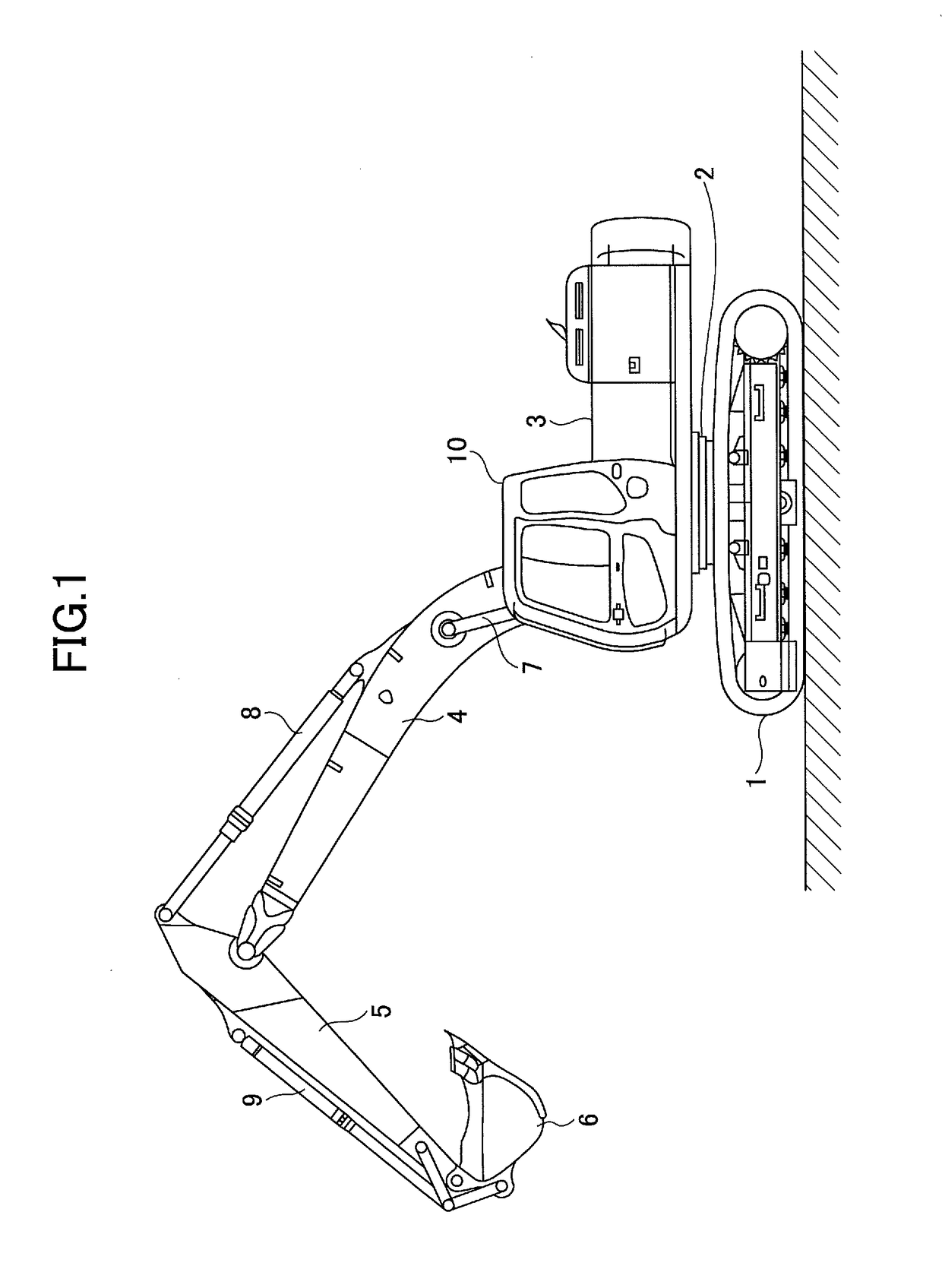
[0070]FIG. 1 is a side view of a hydraulic shovel, which is an example of a hybrid construction machine according to the present invention.

[0071]An upper-part turning body 3 is mounted on a lower-part running body 1 via a turning mechanism 2. A boom 4, an arm 5 and a bucket 6, and a boom cylinder 7, an arm cylinder 8 and a bucket cylinder 9 to drive those cylinders are mounted on the upper-part turning body 3. Moreover, a cabin 10 having a driver's seat, an operation apparatus and a power source, such as an engine or the like, are mounted on the lower-part running body.

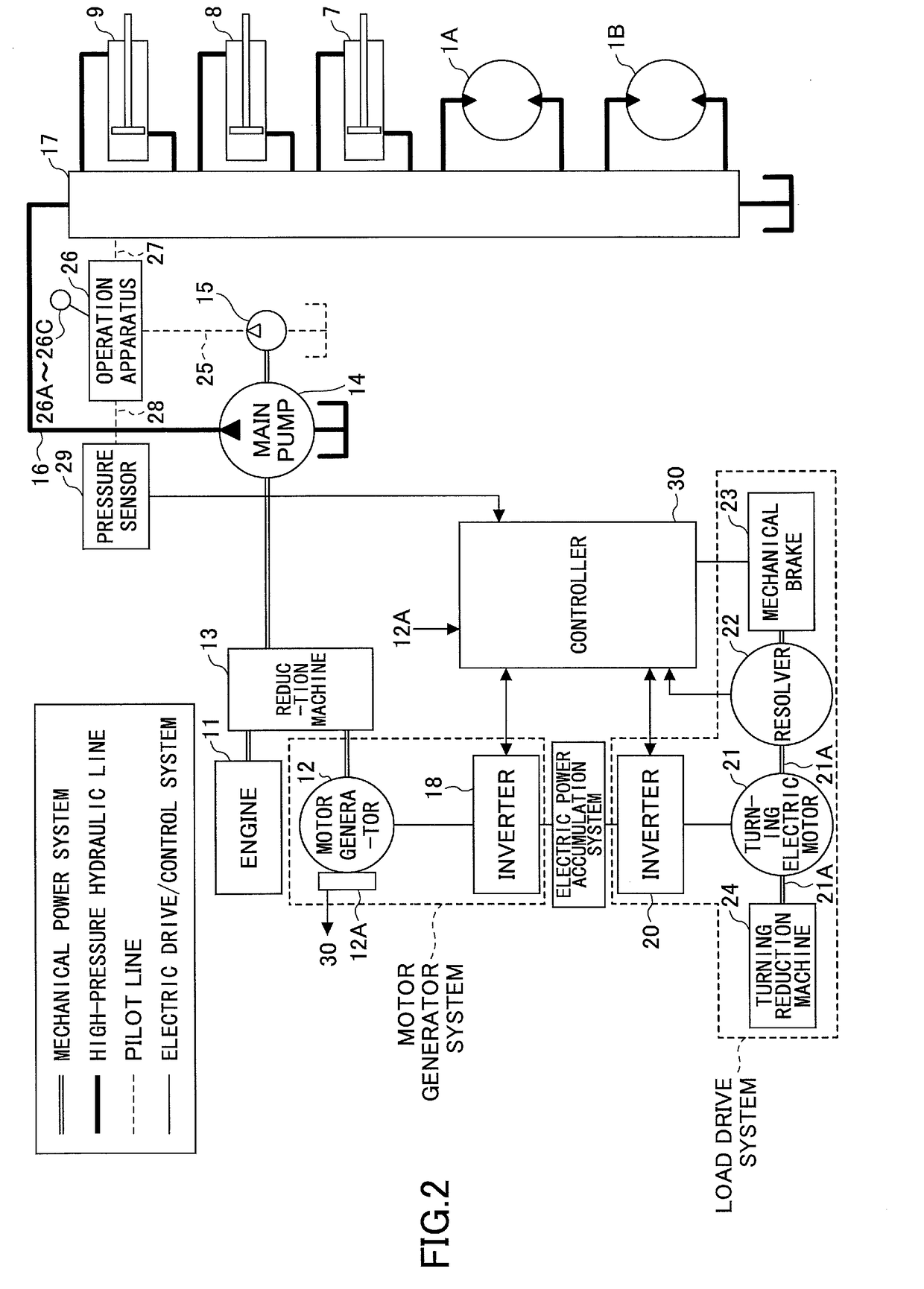
[0072]FIG. 2 is a block diagram illustrating a structure of the hydraulic shovel. In FIG. 2, a double line indicates a mechanical power system, a bold solid line a high-pressure hydraulic line, a dashed line a pilot line, and a solid line an electric drive / control system.

[0073]Both an engine 11 as a mechanical drive part and a motor generator 12 as an assist drive part are connected to an input axis of a reduction mac...

second embodiment

[0137]Next, a description will be given of the present invention.

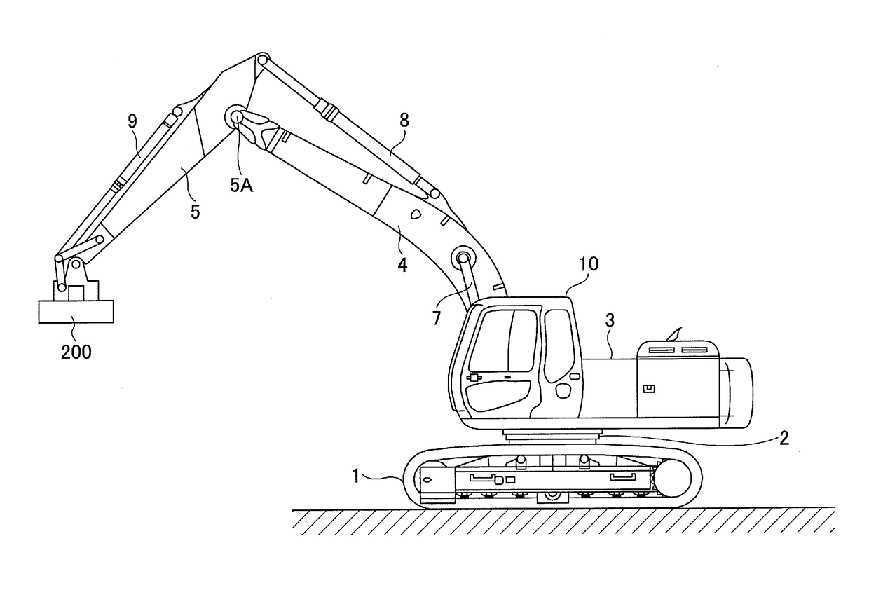
[0138]FIG. 6 is a side view of a lifting magnet type construction machine which is an example of a hybrid construction machine according to the second embodiment of the present invention. The lifting magnet type construction machine is equipped with a lifting magnet 200 instead of the bucket 6 of the hydraulic shovel according to the first embodiment. The lifting magnet 200 is an apparatus for attracting a metal body by an electromagnetic attracting force, and is one of the electric work elements. Thus, it differs from the hybrid construction machine according to the first embodiment also in the structure of the drive control system.

[0139]FIG. 7 is a block diagram illustrating the hybrid construction machine according to the second embodiment. As mentioned above, the hybrid construction machine according to the second embodiment is equipped with the lifting magnet 200. Thus, an inverter to drive the motor generator 12 ...

third embodiment

[0156]A description will be given below of a hybrid construction machine according to the present invention.

[0157]FIG. 8 is a block diagram illustrating a structure of the hybrid construction machine according to the third embodiment of this invention. The hybrid construction machine according to the third embodiment differs from the hybrid construction machine according the second embodiment in that a generator 250 as an electric work element is connected to the DC bus 110 through an inverter 18C.

[0158]In the hybrid construction machine according to the third embodiment, a hydraulic motor 260 is connected to the boom cylinder 7, and a rotation axis of the generator 250 is driven by the hydraulic motor 260. Although, for the sake of convenience of explanation, the hydraulic motor 260 and the generator 250 are separated in FIG. 8, the rotation axis of the generator 250 is mechanically connected to the rotation axis of the hydraulic motor 260 actually.

[0159]The generator 250 is an ele...


PUM


Abstract

A hybrid construction machine includes: a motor generator system connected to an internal combustion engine and performing a motor generator operation; an electric power accumulation system connected to the motor generator system; a load drive system connected to the electric power accumulation system and being driven electrically; an abnormality detection part equipped to the motor generator system, the electric power accumulation system and the load drive system; and a main control part determining whether an abnormality has occurred based on a detection value of the abnormality detection part. When the abnormality determination part determines that an abnormality has occurred, the main control part stops a drive of a drive system in which the abnormality is detected in the load drive system.

Description

CROSS-REFERENCE TO RELATED APPLICATIONS[0001]The present application is a continuation of U.S. patent application Ser. No. 13 / 128,256, filed on May 9, 2011, which is the National Stage of International Application No. PCT / JP2009 / 069057, filed on Nov. 9, 2009, which is based upon and claims priority to Japanese Patent Application No. 2008-288191 filed on Nov. 10, 2008, Japanese Patent Application No. 2008-288192 filed on Nov. 10, 2008, Japanese Patent Application No. 2008-288193 filed on Nov. 10, 2008, Japanese Patent Application No. 2008-288194 filed on Nov. 10, 2008, Japanese Patent Application No. 2009-094860 filed on Apr. 9, 2009, and Japanese Patent Application No. 2009-097250 filed on Apr. 13, 2009, and is also based upon Japanese Patent Application No. 2008-225252 filed on Sep. 2, 2008, Japanese Patent Application No. 2008-277224 filed on Oct. 28, 2008, and Japanese Patent Application No. 2008-279985 filed on Oct. 30, 2008. The disclosures of the prior applications are hereby ...

Claims


Application Information

Patent Timeline
Patent Type & Authority Applications(United States)
IPC IPC(8): E02F9/22F02D29/06E02F9/20B60W30/188B60K6/442B60L50/15B60L50/16B60W10/06B60W10/30B60W20/00
CPCE02F9/2246F02D29/06B60W30/1886E02F9/2075E02F9/2091B60W10/06B60W20/00B60W10/30B60K6/442B60Y2200/25B60Y2200/412B60K6/48B60L1/003B60L1/20B60L3/0023B60L2200/40B60W10/08B60W50/029B60W2510/242E02F9/26E02F9/123E02F9/2058B60L50/61B60L50/16B60L58/24Y02T10/62Y02T10/70Y02T10/7072Y02T10/72B60W20/50
Inventor WU, CHUNNANKANBAYASHI, HIDEAKITAKANASHI, KYOKO
Owner SUMITOMO HEAVY IND LTD
Learn More