
Infrared detection camera

a detection camera and infrared technology, applied in the field of infrared detection cameras, can solve the problems of inability to detect visually, heating which affects any image obtained, and negatively affects the quality of analysis, so as to reduce or eliminate the effect of ambient light and or radiation, portable, lightweight and energy-saving

Active Publication Date: 2017-11-23
LASER & PLASMA TECH LLC
View PDF19 Cites 11 Cited by
  • Summary
  • Abstract
  • Description
  • Claims
  • Application Information

AI Technical Summary

Benefits of technology

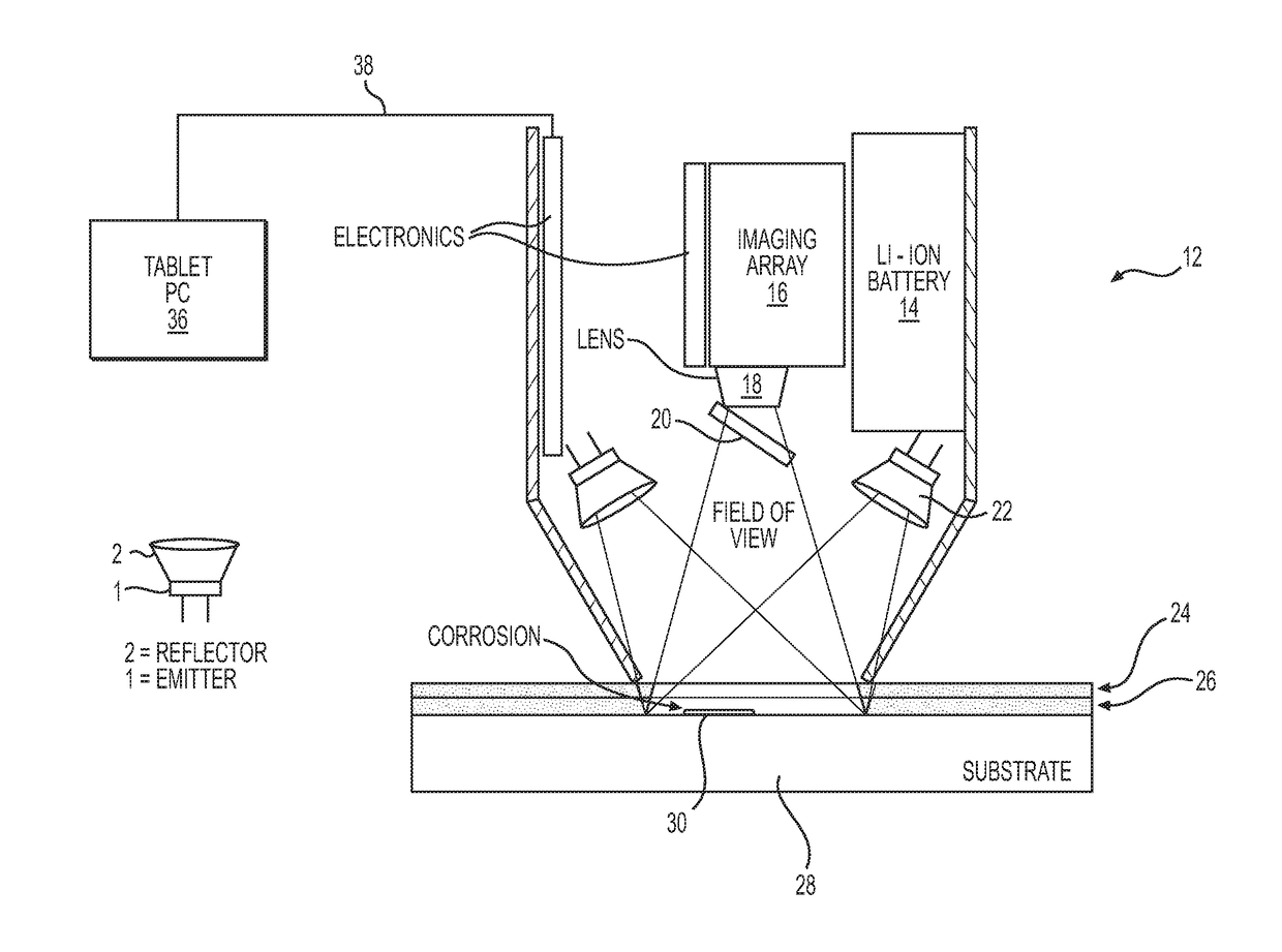
The present invention provides a device for imaging coated surfaces that can capture images in a non-destructive way. The device includes an infrared camera, a lens, a window, an infrared illumination assembly, power source, electronics for controlling and powering the infrared illumination assembly and capturing images, and a housing with a viewing port. The device can capture images of coated surfaces with high energy infrared radiation and has a resolution of 640 by 480 at a frame rate of 120 kHz. The device is designed for use in a variety of applications such as inspection and quality control in manufacturing processes.

Problems solved by technology

Such anomalies occur beneath the coating and are are impossible to detect visually due to the existence of the coating.
Such devices can cause heating which affects any image obtained due to the substrate radiating heat.
Such devices use sunlight or ambient light which negatively affects the quality of the analysis.
Further, such devices are generally held a distance away from the surface being analyzed which allows interference from effects such as stray light, radiation, and thermal radiation.
Finally, many of the prior art devices are not safe for the human eye making them dangerous to use.
This system is complex and requires sensors, microphones, booms and audio processing equipment to function.

Method used


Image

  • Infrared detection camera
  • Infrared detection camera
  • Infrared detection camera

Examples


Embodiment Construction

[0047]The following detailed description is of the best presently contemplated mode of carrying out the invention. This description is not to be taken in a limiting sense, but is made merely for the purpose of illustrating general principles of embodiments of the invention. The embodiments of the invention and the various features and advantageous details thereof are more fully explained with reference to the non-limiting embodiments and examples that are described and / or illustrated in the accompanying drawings and set forth in the following description. It should be noted that the features illustrated in the drawings are not necessarily drawn to scale, and the features of one embodiment may be employed with the other embodiments as the skilled artisan recognizes, even if not explicitly stated herein. Descriptions of well-known components and techniques may be omitted to avoid obscuring the invention. The examples used herein are intended merely to facilitate an understanding of wa...


PUM

PropertyMeasurementUnit
wavelengthaaaaaaaaaa
operational wavelengthaaaaaaaaaa
field of viewaaaaaaaaaa

Abstract

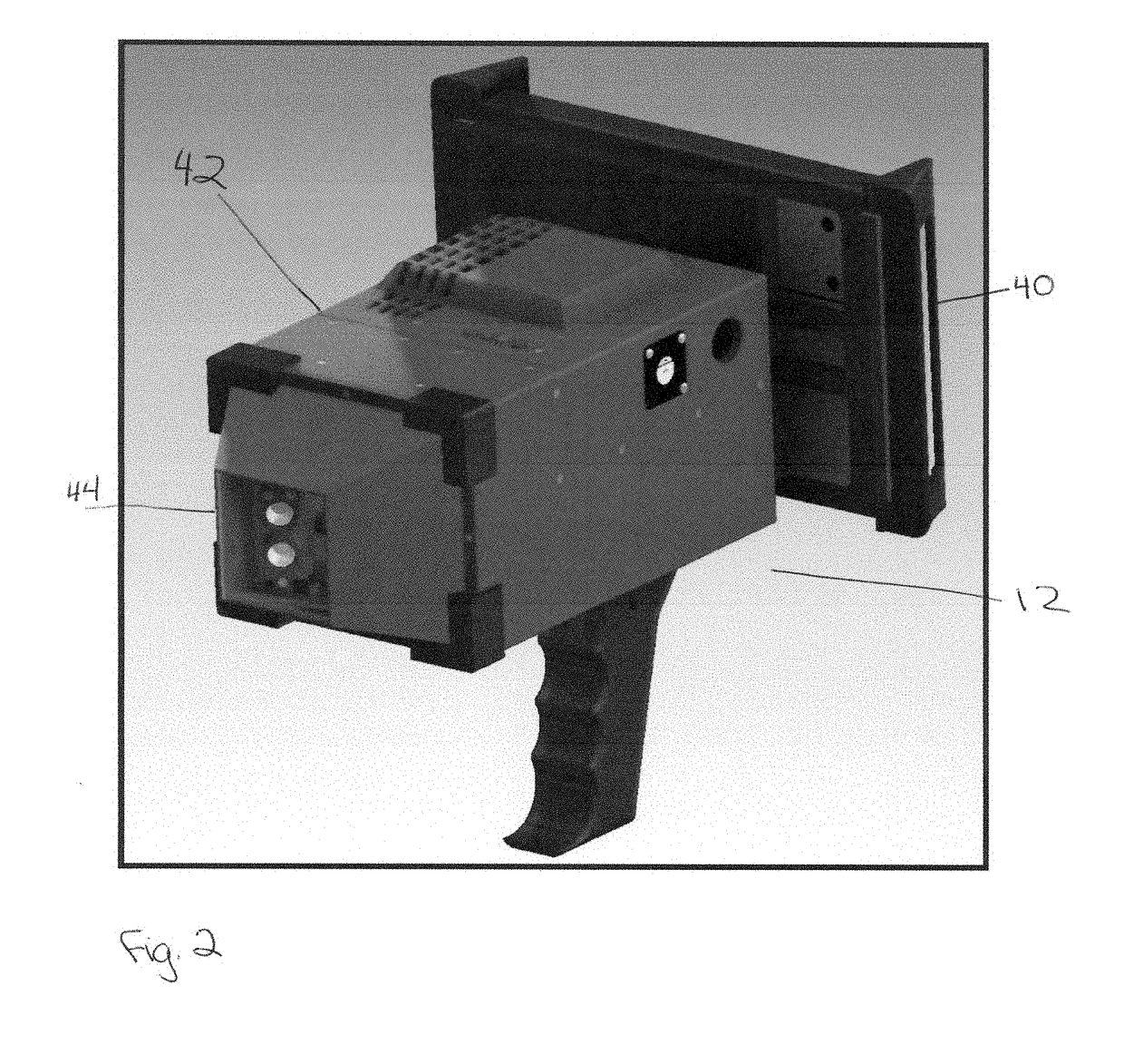
An infrared detection camera for the inspection of coated substrates. A corrosion sensing instrument is handheld, portable, battery powered, compact and lightweight. The camera performs nondestructive, real time imaging of corrosion and defects beneath painted metal or plastics or composite surfaces. The device includes a user-friendly computer interface for real time imaging and image storage capability and is typically used for detecting early stage corrosion beneath painted aircraft aluminum surfaces. The handheld device has a front “open air” imaging port which is designed to be placed in soft contact against the painted surface to be inspected by the instrument. The device includes an infrared camera and infrared lighting to capture an image of the surface. The captured image is transferred to a computer and analyzed to locate imperfections below a coating on a surface.

Description

CROSS REFERENCE TO RELATED APPLICATION[0001]This application claims the benefit of U.S. Provisional Application No. 62 / 274,729, filed Jan. 4, 2016 for “INFRARED DETECTION CAMERA”, incorporated by reference herein in its entirety.BACKGROUND OF THE INVENTION1. Field of the Invention[0002]This invention relates generally to an infrared detection camera and more particularly to an infrared imaging system which can detect anomalies beneath a coating.2. Description of Related Art[0003]This invention has uses in the area of nondestructive evaluation to discover anomalies such as stress fractures, imperfections, or corrosions beneath a coating. Such anomalies occur beneath the coating and are are impossible to detect visually due to the existence of the coating.[0004]Prior art devices generally use broad spectrum light, outside the infrared wavelengths. Such devices can cause heating which affects any image obtained due to the substrate radiating heat. Such devices use sunlight or ambient l...

Claims


Application Information

Patent Timeline
Patent Type & Authority Applications(United States)
IPC IPC(8): G01N21/84G01N21/88
CPCG01N21/8422G01N2021/8427G01N21/8806
Inventor GUPTA, MOOL C.EDRINGTON, ALEXANDER C.HARP, JAMES I.MARSH, WAVERLEY D.SHEN, GUOQING PAUL
Owner LASER & PLASMA TECH LLC
Learn More