
Adaptive voltage modulation circuits for adjusting supply voltage to reduce supply voltage droops and minimize power consumption

Active Publication Date: 2017-11-30
QUALCOMM INC
View PDF0 Cites 9 Cited by
  • Summary
  • Abstract
  • Description
  • Claims
  • Application Information

AI Technical Summary

Benefits of technology

The patent describes a circuit that adjusts voltage to reduce power consumption and prevent timing failures caused by voltage droops. It detects if voltage droops and adjusts the clock signal to the circuit to prevent timing failures. It also counts the number of clock cycles during which voltage droop occurs and increases or decreases voltage accordingly. This adaptive voltage modulation circuit reduces power consumption while ensuring proper circuit operation.

Problems solved by technology

One factor that negatively affects circuit performance is the occurrence of supply voltage droops.
The increase in load current demand causes a surge in power supply current, which results in the supply voltage droop.
The reduction in supply voltage corresponding to a supply voltage droop decreases the speed at which the circuit operates, thus negatively affecting circuit performance.
However, such voltage margins are conventionally set to meet worst-case operating conditions, and thus, can increase power consumption and reduce circuit performance As another example, voltage regulators can be used to sense changes in the load current demand of a circuit, and adjust the supply voltage in response to such changes.
However, voltage regulators are typically too slow to effectively mitigate high frequency supply voltage droops.
However, reducing the frequency of the clock signal in this manner decreases the operating speed of the circuit.
Thus, employing voltage sensors results in a circuit that experiences multiple supply voltage droops to frequently throttle to a lower clock frequency, which limits the performance of the circuit.

Method used


Image

  • Adaptive voltage modulation circuits for adjusting supply voltage to reduce supply voltage droops and minimize power consumption
  • Adaptive voltage modulation circuits for adjusting supply voltage to reduce supply voltage droops and minimize power consumption
  • Adaptive voltage modulation circuits for adjusting supply voltage to reduce supply voltage droops and minimize power consumption

Examples


Embodiment Construction

[0016]With reference now to the drawing figures, several exemplary aspects of the present disclosure are described. The word “exemplary” is used herein to mean “serving as an example, instance, or illustration.” Any aspect described herein as “exemplary” is not necessarily to be construed as preferred or advantageous over other aspects.

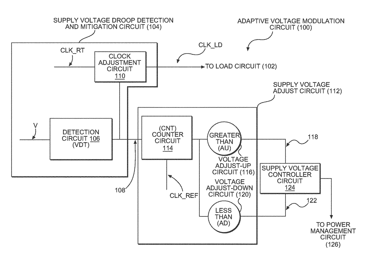
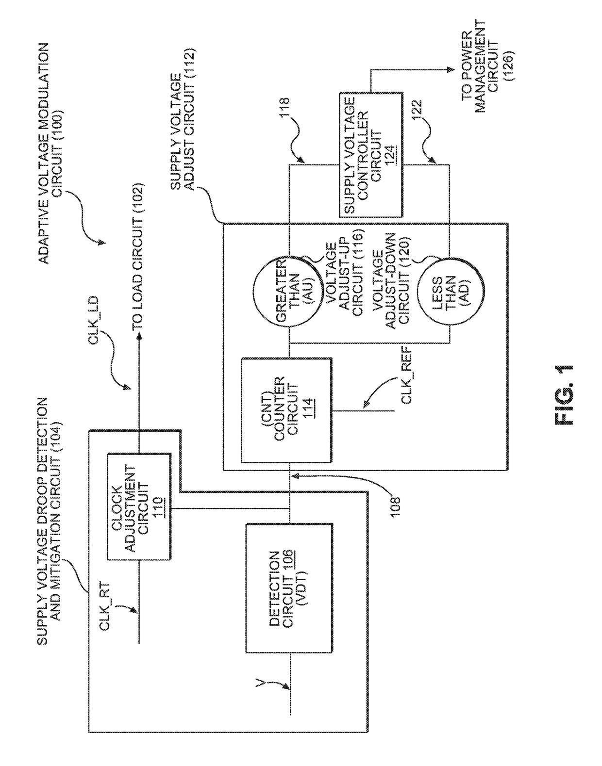
[0017]FIG. 1 illustrates an exemplary adaptive voltage modulation circuit 100 that detects if a supply voltage (V) provided to a load circuit 102 falls below a droop threshold voltage (VDT) (i.e., detects a supply voltage droop). As used herein, a supply voltage droop is a temporary drop or reduction below a particular voltage level of the supply voltage (V) provided by a power supply to the load circuit 102. In response to detecting a supply voltage droop, the adaptive voltage modulation circuit 100 adjusts a load clock signal CLK_LD provided to the load circuit 102 for the duration of the supply voltage droop to mitigate the effects of the supply vo...


PUM


Abstract

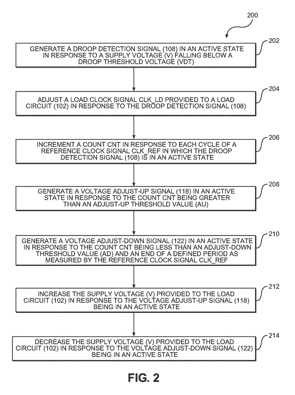
Adaptive voltage modulation circuits for adjusting supply voltage to reduce supply voltage droops and minimize power consumption are provided. In one aspect, an adaptive voltage modulation circuit detects a supply voltage droop by detecting when a supply voltage falls below a droop threshold voltage, and adjusts a clock signal provided to a load circuit in response to a supply voltage droop. The adaptive voltage modulation circuit keeps a count of the number of clock signal cycles during which the supply voltage is below the droop threshold voltage. The adaptive voltage modulation circuit increases the supply voltage in response to the count exceeding an upper threshold value, and decreases the supply voltage in response to the count being less than a lower threshold value at an end of a defined period. The adaptive voltage modulation circuit can reduce the time a load circuit operates with reduced frequency while minimizing power consumption.

Description

PRIORITY CLAIM[0001]The present application claims priority to U.S. Provisional Patent Application Ser. No. 62 / 342,638 filed on May 27, 2016 and entitled “ADAPTIVE VOLTAGE MODULATION CIRCUITS FOR ADJUSTING SUPPLY VOLTAGE TO MITIGATE SUPPLY VOLTAGE DROOPS,” the contents of which is incorporated herein by reference in its entirety.BACKGROUNDI. Field of the Disclosure[0002]The technology of the disclosure relates generally to supply voltage droops, and particularly to adjusting supply voltage to reduce supply voltage droops and power consumption.II. Background[0003]One factor that negatively affects circuit performance is the occurrence of supply voltage droops. A supply voltage droop is a temporary drop or reduction below a particular voltage level of a supply voltage provided by a power supply to one or more elements in a circuit, such as a transistor. Supply voltage droops may be the result of a surge in power supply current provided by the power supply in response to changes in loa...

Claims


Application Information

Patent Timeline
IPC IPC(8): G06F1/32H02M1/08
CPCG06F1/3296G06F1/3287G06F1/324H02M1/08H02M3/157H02M1/0025
Inventor KOLLA, YESHWANT NAGARAJBRIDGES, JEFFREY TODDPATEL, SANJAYSRIDHAR, SHRADDHAPRICE, BURT LEETARR, GABRIEL MARTEL
Owner QUALCOMM INC
Learn More