
Exhaust gas control system for internal combustion engine

a control system and exhaust gas technology, applied in the direction of engines, machines/engines, mechanical equipment, etc., can solve the problems of ablation of the scr catalyst temperature, the temperature of the exhaust gas control element but also the temperature of the scr catalyst inevitably increases, etc., to reduce the quantity of ammonia discharged and enhance the nox purification rate

Active Publication Date: 2017-12-07
TOYOTA JIDOSHA KK
View PDF3 Cites 2 Cited by
  • Summary
  • Abstract
  • Description
  • Claims
  • Application Information

AI Technical Summary

Benefits of technology

The patent text describes a method for reducing ammonia emissions and improving NOx purification in a vehicle's exhaust system. The method involves adding an ammonia precursor to the exhaust system when the engine is running, and stopping the engine to allow the ammonia to adsorb onto the catalyst. This ammonia is then used to reduce NOx when the engine is started again. The method results in a higher NOx purification rate and reduces the amount of ammonia released into the atmosphere.

Problems solved by technology

In such a case, when the temperature increase treatment is executed immediately after the restart of the internal combustion engine, it causes abrupt temperature rise of the SCR catalyst.
Accordingly, not only the temperature of the exhaust gas control element but also the temperature of the SCR catalyst inevitably increases.

Method used


Image

  • Exhaust gas control system for internal combustion engine
  • Exhaust gas control system for internal combustion engine
  • Exhaust gas control system for internal combustion engine

Examples


first embodiment

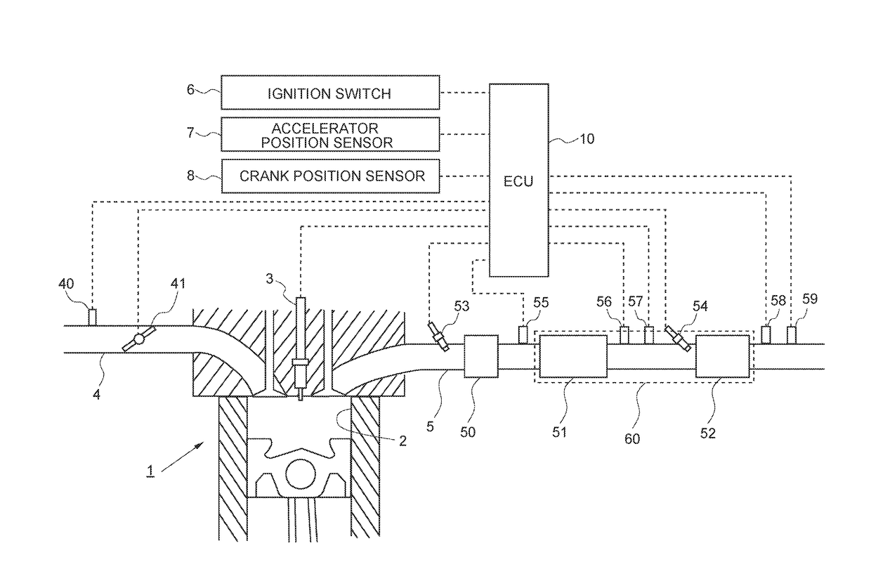
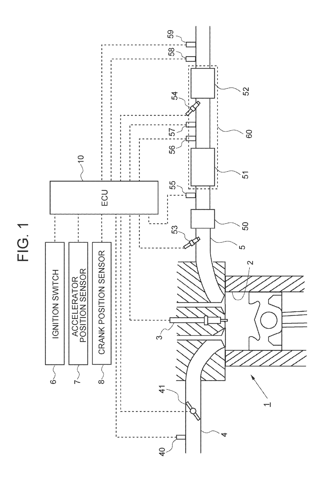
[0028]FIG. 1 illustrates a schematic configuration of an internal combustion engine and an intake and exhaust system thereof according to the present embodiment. The internal combustion engine 1 illustrated in FIG. 1 is a compression ignition type internal combustion engine (diesel engine) that uses gas oil as fuel. However, the present disclosure is also applicable to a spark ignition type internal combustion engine that uses fuel such as gasoline.

[0029]The internal combustion engine 1 includes a fuel injection valve 3 that injects fuel into a cylinder 2. When the internal combustion engine 1 is a spark ignition type internal combustion engine, the fuel injection valve 3 may be configured to inject fuel to an inlet port.

[0030]The internal combustion engine 1 is connected to an intake passage 4. The intake passage 4 is provided with an air flowmeter 40 and a throttle valve 41. The air flowmeter 40 outputs an electrical signal corresponding to the quantity (mass) of intake gas (air) ...

second embodiment

[0075]FIG. 7 illustrates a schematic configuration of an internal combustion engine and an intake and exhaust system thereof according to the embodiment. In the present embodiment, the filter 51 in the first embodiment is replaced with an occlusion reduction NOx catalyst 71 (which may also be referred to as “NSR catalyst 71” below) provided downstream from the oxidation catalyst 50 and upstream from the upstream temperature sensor 56 in the exhaust passage 5. The NSR catalyst 71 has a function to occlude NOx in exhaust gas when an air-fuel ratio of the circumferential atmosphere is a lean air-fuel ratio and to reduce occluded NOx when the air-fuel ratio in the circumferential atmosphere is a rich air-fuel ratio. Here, the term “occlusion” includes a meaning of temporary “adsorption” of NOx onto the NSR catalyst 71. Hereinafter, the NSR catalyst 71 and the SCR catalyst 52 may integrally be referred to as an exhaust gas control apparatus 70. In the present embodiment, the ECU 10 also ...

modified example

[0097]Also in the present embodiment, even in the case where operation of the internal combustion engine 1 is stopped while the SOx poisoning recovery treatment is not executed, it is not necessary to newly adsorb ammonia onto the SCR catalyst 52 after the operation stop of the internal combustion engine 1 when a sufficient quantity of ammonia is already adsorbed onto the SCR catalyst 52 at the moment when the operation of the internal combustion engine 1 is stopped. In short, it is not necessary to add urea water from the urea water addition valve 54 after the operation stop of the internal combustion engine 1.

[0098]Accordingly, in the present embodiment, in the case where operation of the internal combustion engine 1 is stopped while the SOx poisoning recovery treatment is not executed as in the modified example of the first embodiment, addition of the urea water from the urea water addition valve 54 after the operation stop of the internal combustion engine 1 may be executed only...


PUM


Abstract

An exhaust gas control apparatus has an exhaust gas control element other than an SCR catalyst. A temperature increase treatment unit executes temperature increase treatment that increases temperature of exhaust gas flowing into the exhaust gas control apparatus so as to increase the temperature of the exhaust gas control element to a specified target temperature. In this case, when operation of the internal combustion engine is stopped while the temperature increase treatment unit is not executing the temperature increase treatment, addition of an additive to the SCR catalyst from an addition valve is executed after operation stop of the internal combustion engine. When operation of the internal combustion engine is stopped while the temperature increase treatment unit is executing the temperature increase treatment, addition of the additive to the SCR catalyst from the addition valve is not executed after operation stop of the internal combustion engine.

Description

INCORPORATION BY REFERENCE[0001]The disclosure of Japanese Patent Application No. 2016-111902 filed on Jun. 3, 2016 including the specification, drawings and abstract is incorporated herein by reference in its entirety.BACKGROUND1. Technical Field[0002]The present disclosure relates to an exhaust gas control system for an internal combustion engine.2. Description of Related Art[0003]Conventionally, an exhaust gas control system configured to include a selective reduction NOx catalyst (which may also be referred to as an “SCR catalyst” below) in an exhaust passage of an internal combustion engine is known. The SCR catalyst has a function to selectively reduce NOx in exhaust gas with ammonia as a reducing agent. In such an exhaust gas control system, an additive that is ammonia or a precursor of ammonia is added from an addition valve provided in the exhaust passage. Accordingly, ammonia is supplied to the SCR catalyst, so that NOx in exhaust gas is reduced in the SCR catalyst by usin...

Claims


Application Information

Patent Timeline
Patent Type & Authority Applications(United States)
IPC IPC(8): F01N3/20F01N3/035F01N9/00
CPCF01N3/208F01N3/035F01N2610/146F01N2610/02F01N9/002F01N3/0253F01N3/2033F01N3/2066F01N3/28F01N9/00F01N13/009F01N2610/03F01N3/0807F01N3/0842F01N3/0885F01N3/103Y02T10/12Y02T10/40
Inventor ASAURA, SHINYASATO, MASAAKIONO, RYOHEI
Owner TOYOTA JIDOSHA KK
Learn More