Methods of generating energy from cellulosic biofuel waste

Active Publication Date: 2017-12-07
THE BABCOCK & WILCOX CO
View PDF6 Cites 4 Cited by
  • Summary
  • Abstract
  • Description
  • Claims
  • Application Information

AI Technical Summary

Benefits of technology

[0011]In particular embodiments, the waste syrup is fed as a stream or multiple streams directed at the plan area of the fluidized bed, and more particularly the center of the plan area. The waste sy

Problems solved by technology

Unlike the waste products of starch ethanol production, the waste products from the cellulosic ethanol biofuel process typically cannot be sold as either feed or f

Method used


Image

  • Methods of generating energy from cellulosic biofuel waste
  • Methods of generating energy from cellulosic biofuel waste
  • Methods of generating energy from cellulosic biofuel waste

Examples


Embodiment Construction

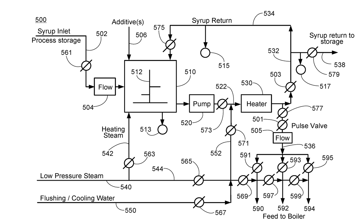
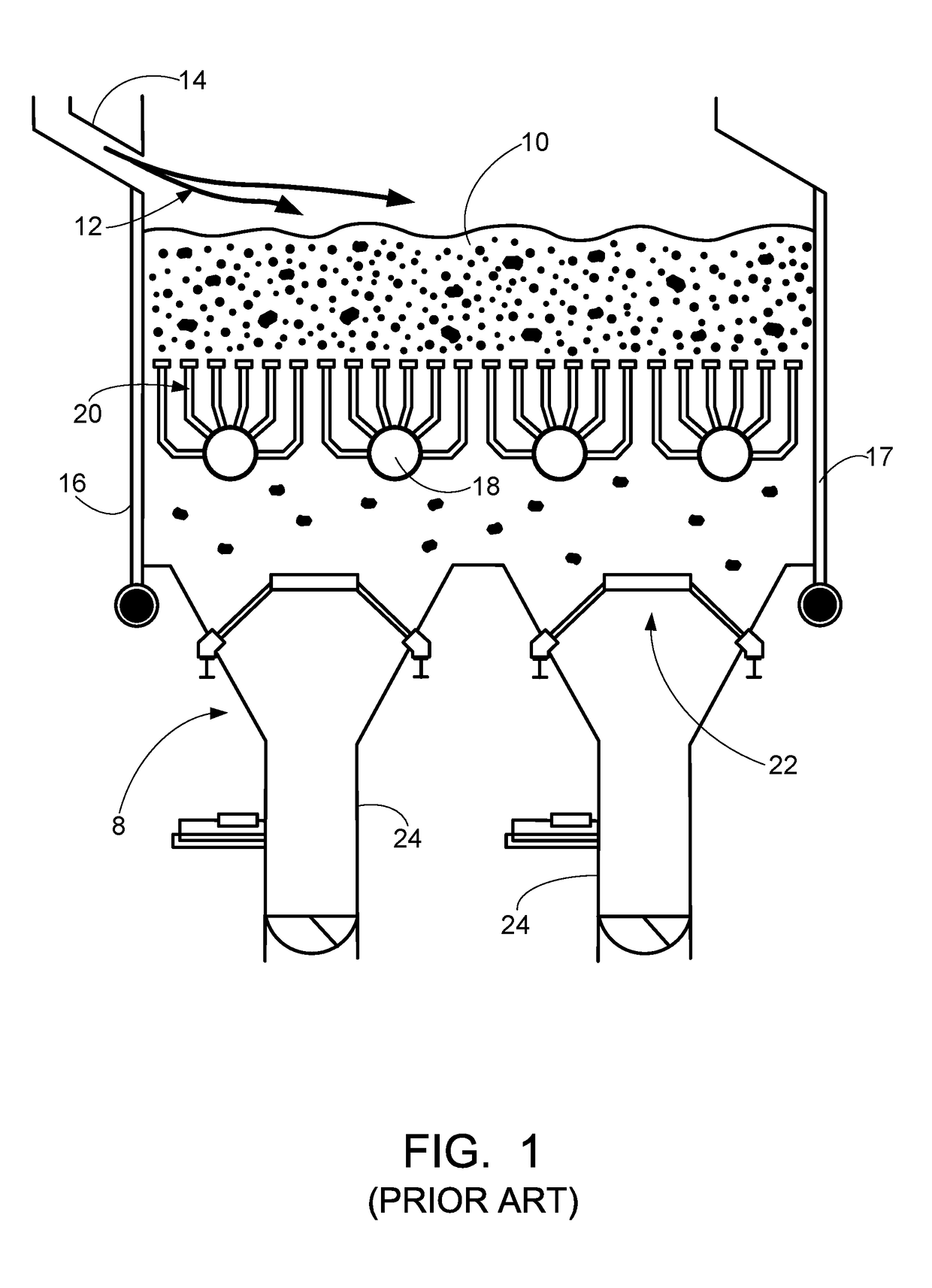
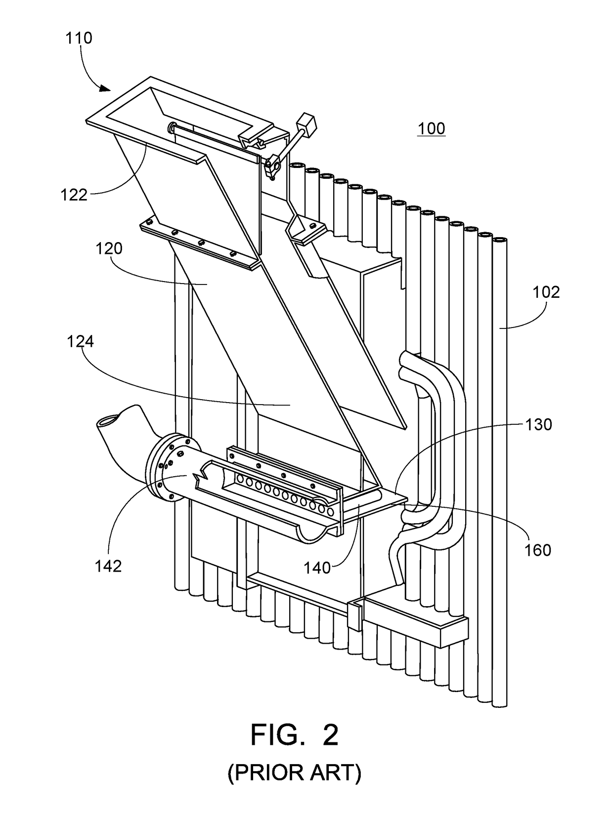
[0026]A more complete understanding of the components, processes, and apparatuses disclosed herein can be obtained by reference to the accompanying drawings. These figures are merely schematic representations based on convenience and the ease of demonstrating the present disclosure, and are, therefore, not intended to indicate relative size and dimensions of the devices or components thereof and / or to define or limit the scope of the exemplary embodiments.

[0027]Although specific terms are used in the following description for the sake of clarity, these terms are intended to refer only to the particular structure of the embodiments selected for illustration in the drawings, and are not intended to define or limit the scope of the disclosure. In the drawings and the following description below, it is to be understood that like numeric designations refer to components of like function.

[0028]The singular forms “a,”“an” and “the” include plural referents unless the context clearly dictat...


PUM


Abstract

Energy is generated from cellulosic biofuel waste streams, specifically a lignin filter cake and a waste syrup, by combusting these waste products in a fluidized bed combustor under specified conditions. The heat and steam generated can be used to generate electricity and/or in cellulosic biofuel production processes.

Description

BACKGROUND[0001]The present disclosure relates to the use of waste streams to generate energy. In particular, waste streams formed by the production of cellulosic ethanol are used herein. The disclosure also relates to fluidized-bed boilers, such as a bubbling fluidized-bed (BFB) or circulating fluidized-bed (CFB) boiler, for combusting such products and materials, and to related arts.[0002]During combustion, the chemical energy in a fuel is converted to thermal heat inside the furnace of a boiler. The thermal heat is captured through heat-absorbing surfaces in the boiler to produce steam. Fuels used in the furnace include a wide range of solid, liquid, and gaseous substances. Combustion transforms the fuel into a large number of chemical compounds. In some applications, solid biomass waste byproducts are used as fuel for the fluidized-bed boiler.[0003]Fluidized-bed boilers are one way to burn solid fuels. Generally speaking, a fluidized-bed boiler includes a bed formed from a stack...

Claims


Application Information

Patent Timeline
IPC IPC(8): F23G5/30C12P7/06F23C10/04C08L97/00C08L97/02F23G5/12C12P7/10
CPCF23G5/30C08L97/02C08L97/005F23C10/04F23G5/12C10L2290/06C10L2200/04C12P7/10C10L2200/0469C10L2290/02C12P7/06C10L5/445F23C10/22F23C2206/102F23G2209/12F23G2209/26F23G2900/50007Y02E20/12Y02E50/10Y02E50/30Y02P20/133
Inventor DESELLEM, JAMES F.FLYNN, THOMAS J.HEIL, KARL M.WELLS, ERIC L.
Owner THE BABCOCK & WILCOX CO
Why Eureka
Try Eureka