
Electro-catalytic recharging composition

Inactive Publication Date: 2008-11-13
BRICOLEUR PARTNERS LP
View PDF3 Cites 4 Cited by
  • Summary
  • Abstract
  • Description
  • Claims
  • Application Information

AI Technical Summary

Benefits of technology

[0008]In one aspect of the invention, a high-surface electro-catalytic recharging composition is provided. The composition may comprise catalytic metal particles, preferably at the nanoscale, and an ion-conducting medium. When immersed within an electrolyte, the composition can move freely and the nanoparticles may substantially make contact with or infuse into a metallic surface that may also have extremely high surface area. This metallic surface may function as both a portion of the electrode and a current collector used in conjunction with the electro-catalytic composition in an electrochemical device such as a fuel cell or electrolyzer.
[0009]With at least one preferred embodiment, regardless of electrochemical cell or system design, the liquid electro-catalytic recharging solution can be removed from the device and replaced with fresh solution if so desired. For example, should the electrolyte and / or nanoparticles in the fluidized bed electrode decompose over time or extended use, it can be discharged or drained from the device and replaced with new solution. This process can be repeated for the duration of device life to maintain good performance.
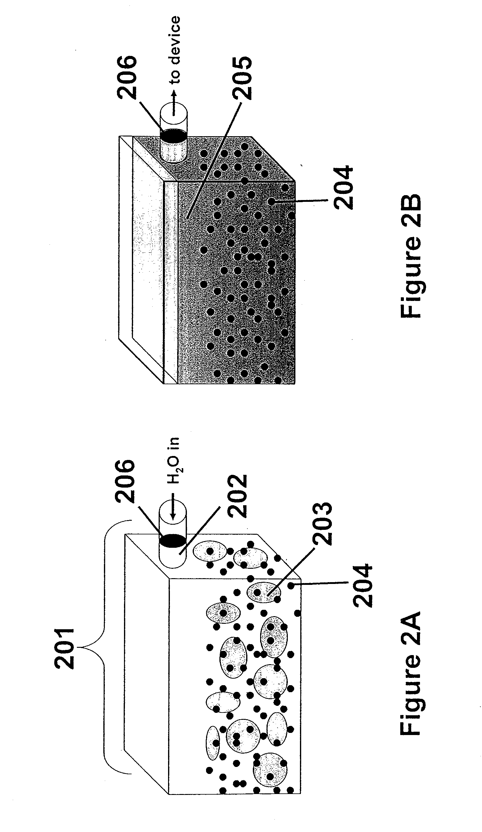
[0012]In another embodiment of the invention, the electro-catalytic charging composition comprises a solid electrolyte and catalyst nanoparticles. At least one advantage of a solid phase is that storage of the inventive composition requires less space. In one application, the composition may be stored within a cartridge, for example, so that when it is desired to replace the electro-catalytic composition in the device, water can be inserted in a new cartridge and injected on-site.
[0013]Preferably, the container that stores the electro-catalytic composition should be configured to have a delivery port to the electrochemical device for ease of handling. This will reduce the possibility of skin contact and spills. In the case of the solid electro-catalytic charging composition, an additional port on the storage container may be useful, for the introduction of water before insertion into the device.
[0016]Conversely, in the fluidized bed system, a portion or all of the electro-catalytic charging composition could be flushed from the system and replaced with fresh electro-catalytic charging material as needed. An additional advantage to the rapid flushing and replacement of the composition is that in many electrochemical devices, the concentration of electrolyte fluctuates over time or the electrode degrades. When this occurs, the electrode may not be operating at its highest efficiency. With respect to the described system, the spent electro-catalytic composition can be removed from the cell and be replaced with a fresh solution. In this case, operation of the electrochemical device may function similar to a gasoline tank on an automobile, namely to refill as fuel is depleted. Other advantages may include, depending upon the configuration, circumstances, and environment, the ability to scale the electrode to a wide variety of sizes, higher power, and the ability to minimize agglomeration by using nanosized particles.

Problems solved by technology

In many conventional devices, low catalyst utilization in the electrodes, cell resistance, inefficient movement of electrolyte, and inefficient collection of reaction products from the electrolyte stream contribute to significant efficiency loss.
This strategy does increase efficiency; however, it also lowers the amount of products that can be produced at a given time.
However, this noble metal is a rapidly depleting non-renewable resource and is consequently expensive.
The associated cost of a platinum deposited electrode, typically loaded anywhere from 2-8 mg / cm2, is widely considered to be a hurdle to widespread commercialization.
However, the use of FBRs is relatively unexplored in conjunction with electrochemical cells, and has not been previously demonstrated with catalyst nanoparticles.

Method used


Image

  • Electro-catalytic recharging composition
  • Electro-catalytic recharging composition
  • Electro-catalytic recharging composition

Examples


Embodiment Construction

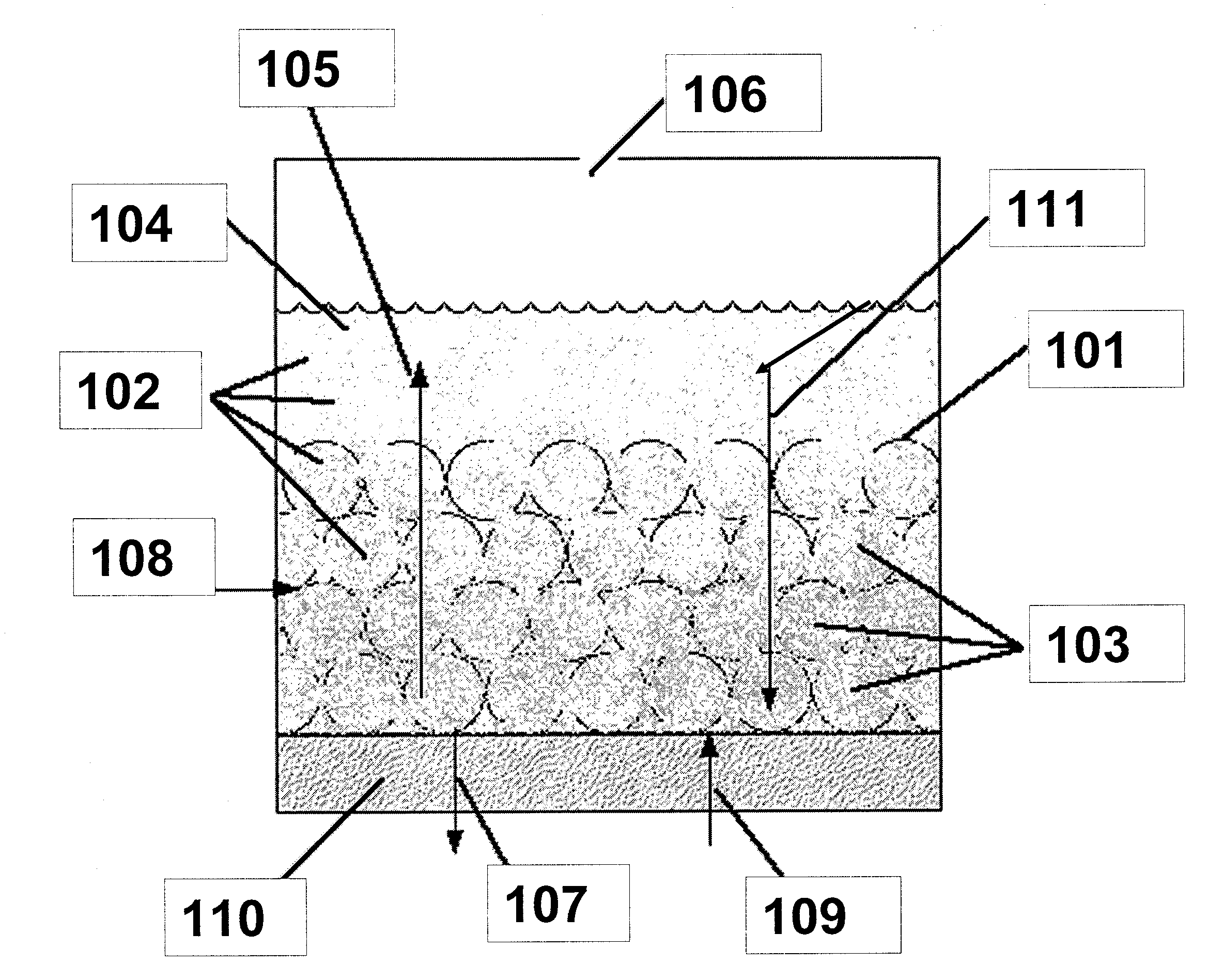
[0021]In an electrochemical device employing a fluidized bed, a significant portion of the electrode may comprise catalytic metal particles dispersed in an ion-conducting solution, also known as an electro-catalytic charging composition. Because a significant portion of the electrode is fluidized, the electrochemical cell can be configured to operate horizontally, vertically, or any degree in between. Additionally, the electro-catalytic charging composition may be employed in a variety of cell designs, including, but not limited to flat plate or tubular structures.

[0022]Referring to FIG. 1, the inventions described herein may be used in an electrochemical device, a portion of which is shown with a high surface area metallic surface infused with electro-catalytic solution. In this example, the inventive composition is used in a water electrolysis device. Metallic surface 101 is preferably highly reticulate or porous, and can accommodate the infusion of nanoparticles 102 (shown as dot...


PUM


Abstract

A composition useful for the fueling and refueling of electrochemical devices is described. The composition comprises an ion-conducting medium such as an electrolyte, and catalyst nanoparticles. Unlike traditional electrodes, such as those typically used in electrolyzers and fuel cells, the inventive composition may be quickly drained from the device and refilled to maintain maximum cell performance. In addition, the electro-catalytic charging composition can be stored as a solid for safe handling; for example in a portable cartridge.

Description

BACKGROUND OF THE INVENTION[0001]1. Technical Field[0002]The inventions disclosed herein generally relate to a composition used for the fueling and re-fueling of electrochemical devices.[0003]2. Related Art[0004]A fuel cell is a device that converts chemical energy directly into electrical energy. They typically operate with higher efficiencies than traditional combustion engines. In addition, emission of greenhouse gasses from fuel cells is reduced or eliminated. The prospect of affordable, clean fuel for stationary and transportation applications are several of the driving forces behind the Hydrogen Economy, where the energy infrastructure is based on hydrogen instead of oil. Liquid hydrocarbon fuels, such as methanol, are also advantageous in fuel cells. Fuel cell electrodes and devices have been previously described in U.S. Ser. No. 60 / 896,722. The disclosure of this application is incorporated herein by reference.[0005]Devices that are configured to electrochemically convert re...

Claims


Application Information

Patent Timeline
IPC IPC(8): H01M8/18
CPCC25B9/162H01M4/9016H01M8/188Y02E60/528Y10S977/948Y02E60/50C25B9/40
Inventor MALONEY, KEVIN D.DOPP, ROBERT
Owner BRICOLEUR PARTNERS LP
Learn More