Heat spreader with a liquid-vapor separation structure
- Summary
- Abstract
- Description
- Claims
- Application Information
AI Technical Summary
Benefits of technology
Problems solved by technology
Method used
Image

Examples
first embodiment
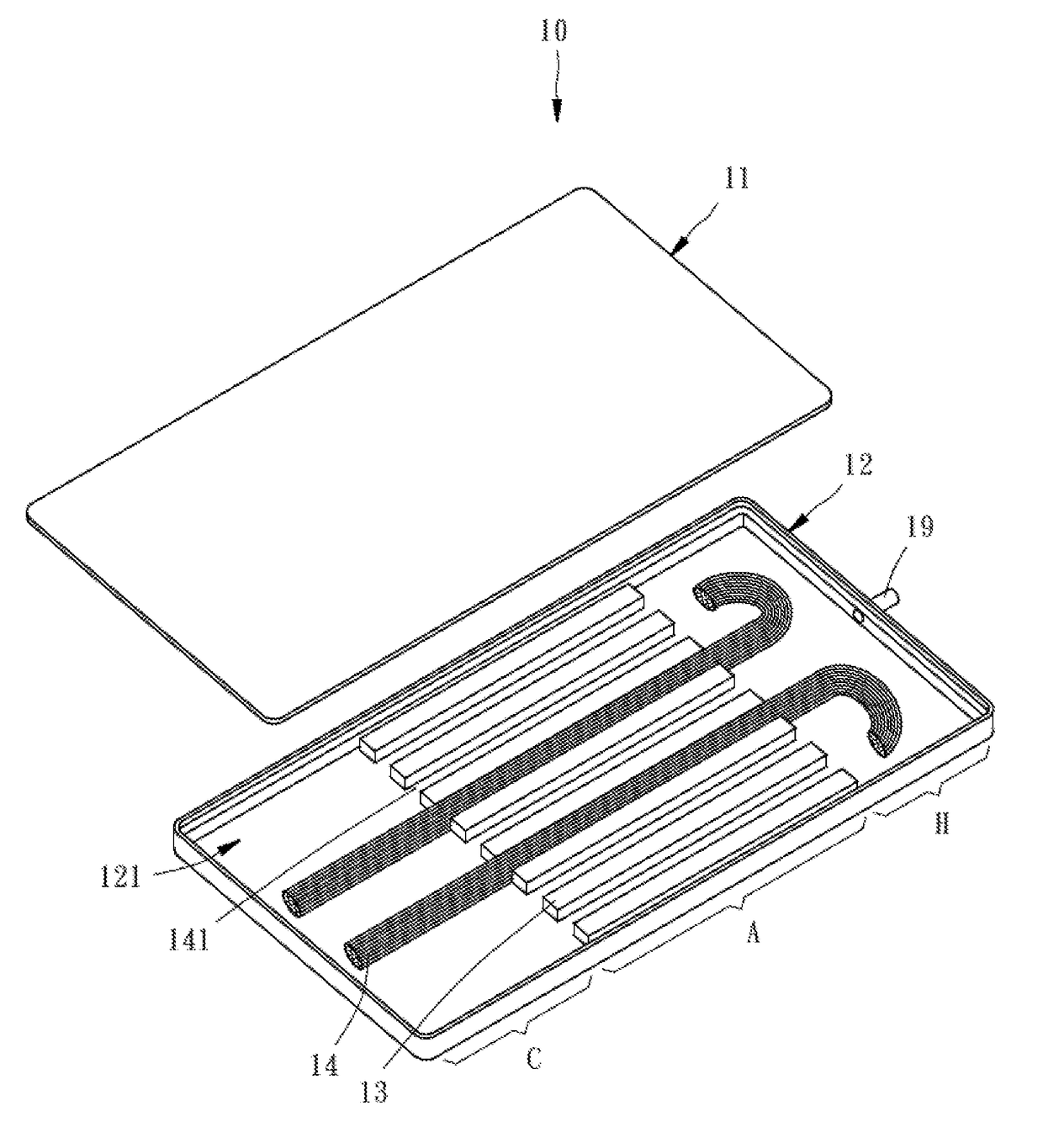
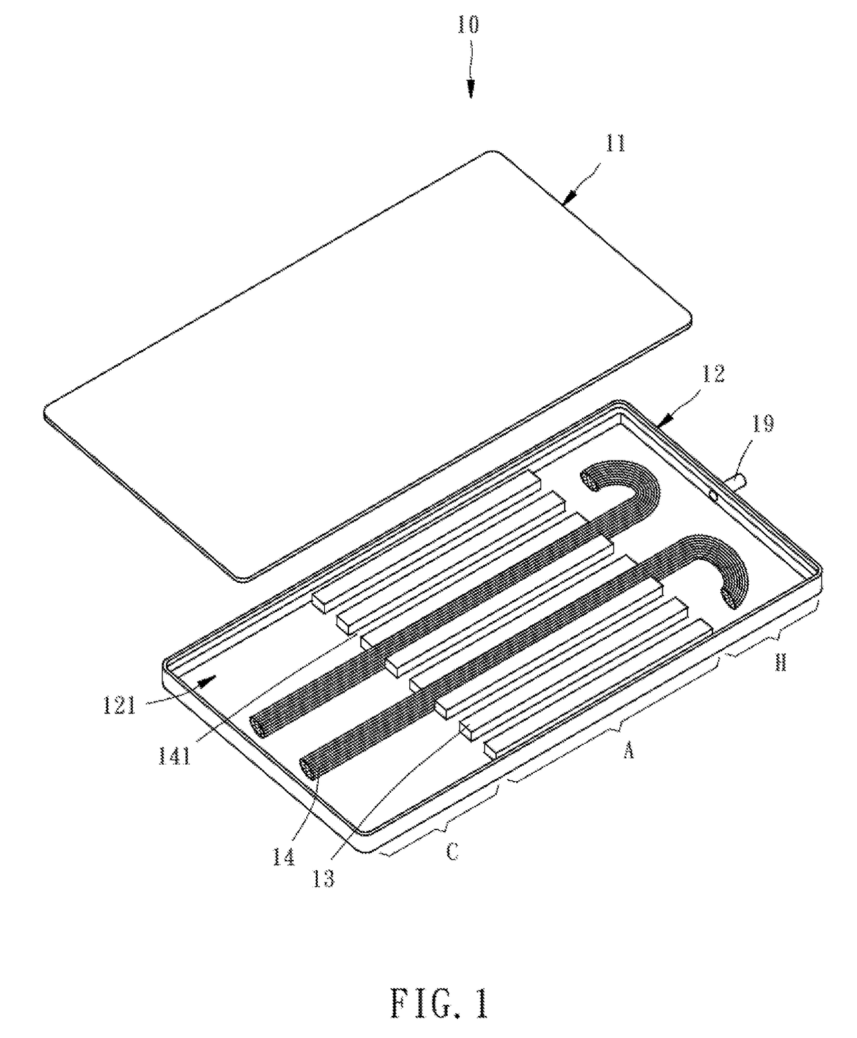
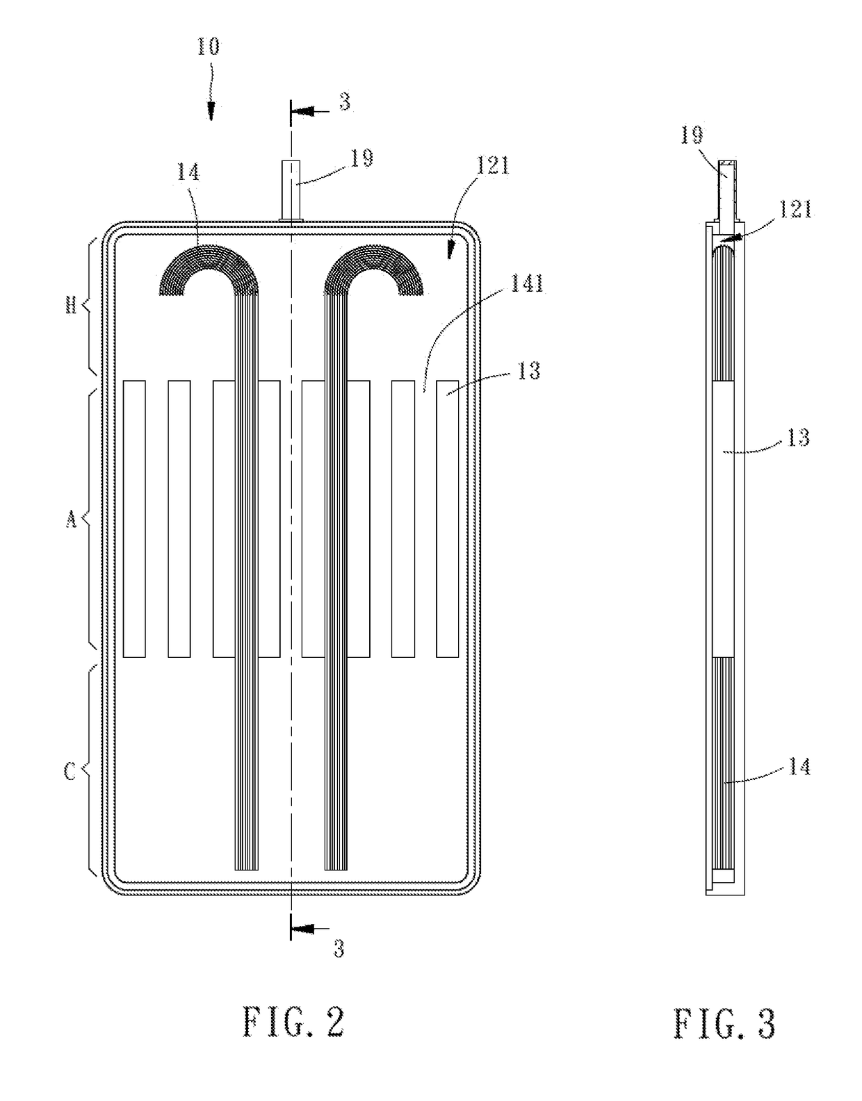
[0026]Referring to FIGS. 1-4, a heat spreader with a liquid-vapor separation structure in accordance with the present invention is shown. The heat spreader 10 comprises at least one first panel 11, a second panel 12, a plurality of spacer members 13, at least one piece of first wick material 14 and a working fluid (not shown).
[0027]The at least one first panel 11 is bonded to the second panel 12. In this first embodiment, the number of the at least one first panel 11 is 1. Further, the first panel 11 and the second panel 12 define therebetween at least one enclosed accommodation chamber 121. In this first embodiment, the number of the at least one accommodation chamber 121 is 1. Further, at least one vapor discharge tube 19 is disposed in the connection area between the first panel 11 and the second panel 12. In this first embodiment, the number of the at least one vapor discharge tube 19 is 1. The vapor discharge tube 19 has one end thereof disposed in communication with the accomm...
second embodiment
[0036]The second panel 22 has a second wick material 28 sintered thereto. This second wick material 28 can be disposed in the second panel 22 within the heat-absorbing zone H2 and / or the condensing zone C2. In this second embodiment, the two pieces of first wick material 24 are disposed in contact with the second wick material 28.
[0037]The second wick material 28 can be selected from copper powder or copper mesh. In this second embodiment, the second wick material 28 is a copper mesh.
[0038]In this second embodiment, a respective certain area of the second wick material 28 is respectively sintered to the heat-absorbing zone H2 and the condensing zone C2 in the second panel 22 of the heat spreader 20, enabling the heat-absorbing zone H2 to have a relatively higher working fluid carrying capacity. Further, the second wick material 28 effectively and evenly carries the working fluid, enhancing the evapotranspiration efficiency of the working fluid. Further, the arrangement of the second...
third embodiment
[0041]The third wick material 38 can be selected from copper powder or copper mesh. In this third embodiment, the third wick material 38 is made from copper mesh.
[0042]In this third embodiment, the added structure of the two recessed portions 322 of the heat spreader 30 increase the working fluid storage capacity of the condensing zone C3; the two pieces of first wick material 34 are used to guide the working fluid from the condensing zone C3 back to the heat-absorbing zone H3. Further, changing the number of the component parts of the heat spreader 30 can relatively changing the cooling efficiency. The other structural features of this third embodiment and the effect this third embodiment can achieve are same as the aforesaid first embodiment, and thus, it is unnecessary to repeat them here.
[0043]Referring to FIG. 9, a heat spreader 40 in accordance with a fourth embodiment of the present invention is shown. This fourth embodiment is substantially similar to the aforesaid first emb...
PUM
 Abstract
Description
Claims
Application Information
 - Generate Ideas
- Intellectual Property
- Life Sciences
- Materials
- Tech Scout
- Unparalleled Data Quality
- Higher Quality Content
- 60% Fewer Hallucinations
Browse by: Latest US Patents, China's latest patents, Technical Efficacy Thesaurus, Application Domain, Technology Topic, Popular Technical Reports.
© 2025 PatSnap. All rights reserved.Legal|Privacy policy|Modern Slavery Act Transparency Statement|Sitemap|About US| Contact US: help@patsnap.com