Defect detection method and defect detection apparatus

a technology of defect detection and detection method, applied in the direction of instruments, structural/machine measurement, elasticity measurement, etc., can solve the problem of time-consuming scanning

Active Publication Date: 2017-12-07
SHIMADZU CORP
View PDF8 Cites 25 Cited by
  • Summary
  • Abstract
  • Description
  • Claims
  • Application Information

AI Technical Summary

Benefits of technology

[0034]According to the defect detection method and apparatus of the present invention, because a measurement region of a target object is inspected at one time, inspection can be performed in a short time period. Further, since displacements in the normal direction (out-of-plane direction) at each point in the measurement region on the surface of the target object are measured with respect to at least three mutually-different phases of an elastic wave that is generated in the target object, a complete vibrational state of the elastic wave at all locations in the measurement region can be reproduced regardless of the size of a wavelength (with respect to the measurement region) of the elastic wave, and thus inconsistencies in the defect detection capability that depend on the location within the measurement region do not arise.

Problems solved by technology

However, since the detection laser (probe laser) of a laser interferometer is spot-like, it is necessary to move the laser spot across (or scan) the entire inspection region of a target object, and a problem is that such scanning takes time.

Method used


Image

  • Defect detection method and defect detection apparatus
  • Defect detection method and defect detection apparatus
  • Defect detection method and defect detection apparatus

Examples


Embodiment Construction

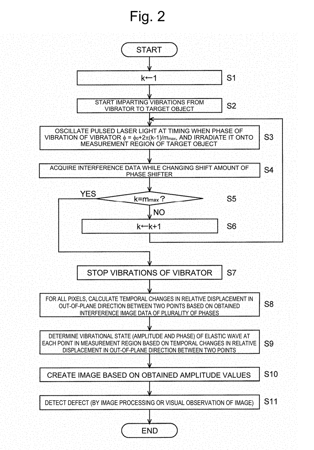
[0039]An embodiment of the defect detection method and defect detection apparatus according to the present invention will now be described using FIG. 1 to FIG. 4A and FIG. 4B.

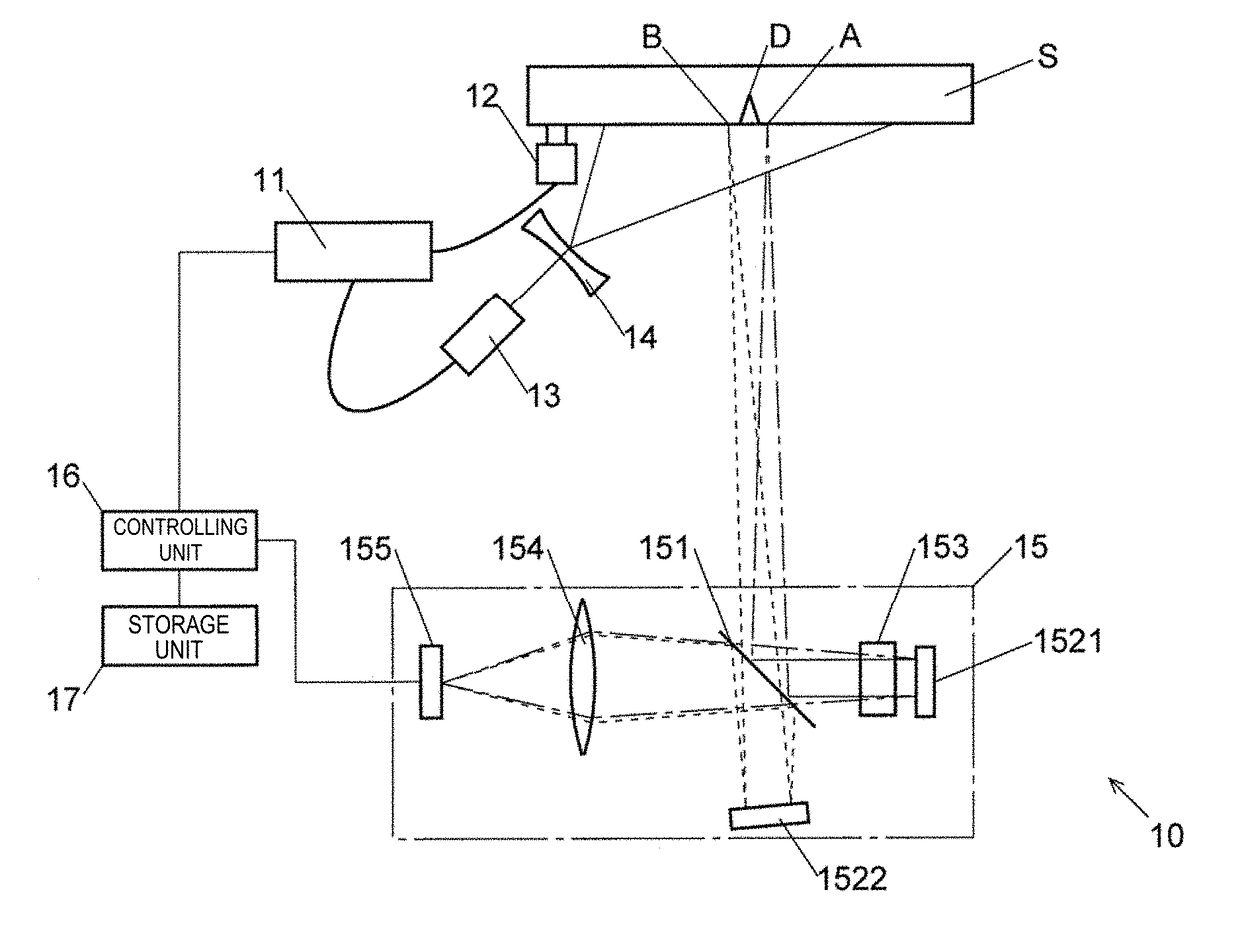
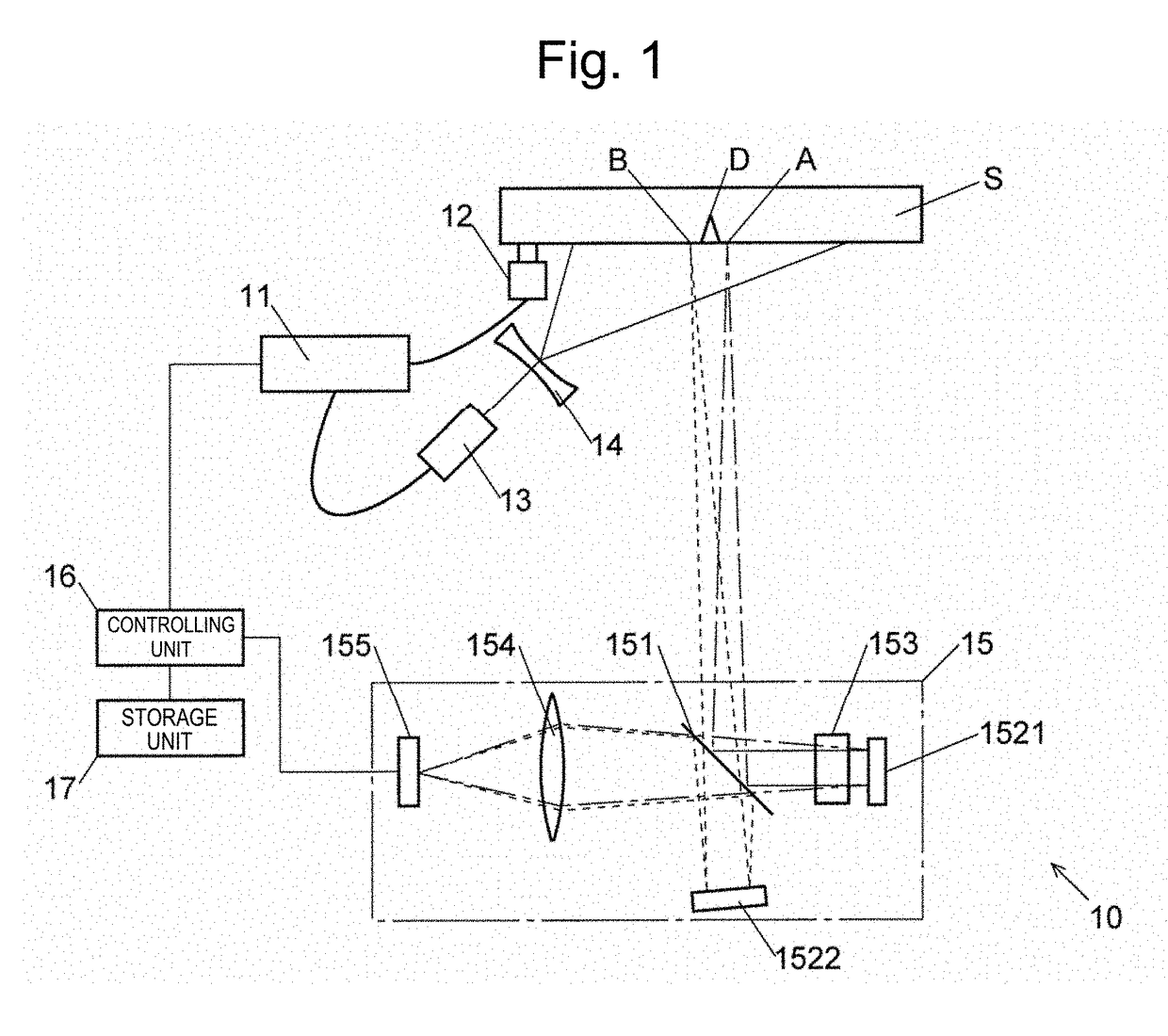
[0040]FIG. 1 is a schematic configuration diagram of a defect detection apparatus 10 of the present embodiment. The defect detection apparatus 10 includes a signal generator 11, a vibrator 12, a pulsed laser light source 13, an illumination light lens 14, a speckle shearing interferometer 15, a controlling unit 16 and a storage unit 17.

[0041]The signal generator 11 is connected by a cable to the vibrator 12, and generates an alternating current signal and sends the alternating current signal to the vibrator 12. The vibrator 12 is caused to contact against a target object (object under inspection) S and used. The vibrator 12 receives the alternating current signal from the signal generator 11 and converts the signal to mechanical vibrations, and imparts the mechanical vibrations to the target object S. By this m...


PUM

PropertyMeasurementUnit
angleaaaaaaaaaa
defect detectionaaaaaaaaaa
displacementsaaaaaaaaaa

Abstract

A defect detection apparatus is provided that can inspect a measurement region of a target object at one time and without inconsistencies arising within the measurement region. A defect detection apparatus 10 includes: a generation unit (signal generator 11 and vibrator 12) for generating an elastic wave in a target object S; an illumination unit (pulsed laser light source 13 and illumination light lens 14) for performing stroboscopic illumination onto a measurement region of a surface of the target object S; and a displacement measurement unit (speckle shearing interferometer 15) for collectively measuring displacements in a normal direction at each point of the measurement region with respect to at least three mutually-different phases of the elastic wave by controlling a phase of the elastic wave and a timing of the stroboscopic illumination. Defects in the measurement region are detected based on the displacements in the normal direction at each point of the measurement region with respect to at least three phases that are obtained by the displacement measurement unit.

Description

TECHNICAL FIELD[0001]The present invention relates to a method and an apparatus for non-contact detecting defects on a surface of and inside an object such as a concrete or steel structure.BACKGROUND ART[0002]A laser ultrasound method is one technique for non-contact detecting and measuring defects on a surface of and inside an object such as a concrete or steel structure. In the laser ultrasound method, the surface displacement of a target object is measured by generating an elastic wave in the target object, and meanwhile casting a laser beam at the target object and detecting reflected light with a laser interferometer. Because displacements caused by an elastic wave change discontinuously across defects, defects can be detected by measuring the distribution of the displacements. However, since the detection laser (probe laser) of a laser interferometer is spot-like, it is necessary to move the laser spot across (or scan) the entire inspection region of a target object, and a pro...

Claims


Application Information

Patent Timeline
Patent Type & Authority Applications(United States)
IPC IPC(8): G01B9/02G01N21/17G01N21/88
CPCG01B9/02095G01N21/8806G01N2201/0697G01N2021/8838G01N2201/06113G01N21/1702G01N21/88G01N2021/1706G01B9/02098G01B17/00G01M5/0033G01M5/0066G01M5/0091G01M7/00G01N29/043G01N29/045G01N29/2418G01N2291/0232G01N2291/0234G01B9/02096
Inventor HATAHORI, TAKAHIDETAKUBO, KENJI
Owner SHIMADZU CORP
Why Eureka
Try Eureka