Industrial ct scanning test system

a test system and computed tomography technology, applied in the field of sample scanning, can solve the problems of large volume and weight of conventional loading devices, adversely affecting the application of ct techniques in mechanics analysis, and difficult to directly place them in the industrial ct machine, so as to improve the simulation accuracy of the system

Active Publication Date: 2017-12-07
CHINA UNIV OF MINING & TECH (BEIJING)
View PDF1 Cites 10 Cited by
  • Summary
  • Abstract
  • Description
  • Claims
  • Application Information

AI Technical Summary

Benefits of technology

[0008]An industrial CT scanning test system is provided according to the present application, which can achieve real-time loading of a test sample and improve simulation accuracy of the system, and can achieve multi-directional loading on the sample, to meet test requirements.

Problems solved by technology

These restrictions adversely affect the application of the CT technique in mechanics analysis to a great extent.
A loading device is indispensable in mechanics experiments; however, a conventional loading device generally has a large volume and weight, and is hence difficult to be directly placed in the industrial CT machine to be used in the scanning process.
This loading method has a low accuracy, and once the loading is finished, the load applied to the test sample is not adjustable.
Firstly, the sample cannot be too small; otherwise, the analysis may be influenced by a dimensional effect such that a desired experimental result cannot be obtained.
However, the increase in the size of the sample may inevitably result in the increase in the size of the loading device, thus causing a series of issues such as, rays are difficult to penetrate the sample, the loading tonnage is increased, and the resolution ratio of the image is decreased.
Secondly, loading schemes are generally complicated; to simulate a stress state of the geotechnical material in practical engineering, a simple uniaxial tensile and compression experiment is not sufficient, various complicated loading experiments are further required, such as multi-axial compression experiment, percolation experiment, and hydraulic fracturing experiment.

Method used


Image

  • Industrial ct scanning test system
  • Industrial ct scanning test system
  • Industrial ct scanning test system

Examples


Embodiment Construction

[0051]An industrial Computed Tomography (CT) scanning test system is provided according to the present application, which can achieve real-time loading of a test sample and improve simulation accuracy of the system, and can achieve multi-directional loading on the sample, to meet test requirements.

[0052]For those skilled in the art to better understand technical solutions of the present application, the present application is described in detail in conjunction with drawings and embodiments hereinafter.

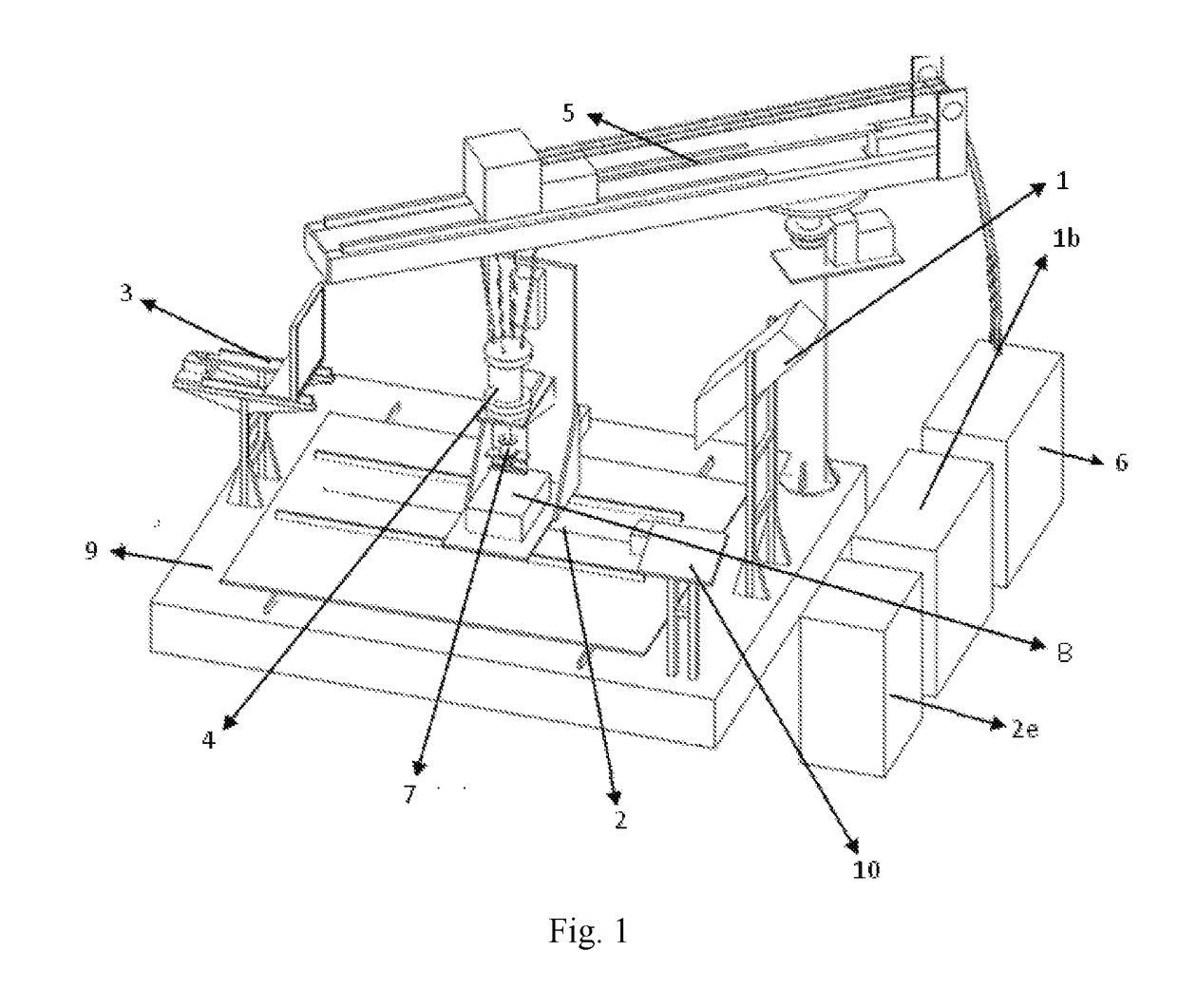
[0053]Reference is made to FIG. 1, which is a schematic view showing the structure of an industrial CT scanning test system according to an embodiment of the present application.

[0054]An industrial CT scanning test system is provided according to the present application. This system includes a test base 9, a multi-axis motion swivel table 2 supported on the test base 9, a ray generator 1, an image acquisition device 3, a fluid pressure loading device 4, and a control device 6. The mult...


PUM

PropertyMeasurementUnit
pressureaaaaaaaaaa
radial dimensionaaaaaaaaaa
stress-aaaaaaaaaa

Abstract

An industrial CT scanning test system. The test system includes a test base, a multi-axis motion swivel table supported on the test base, a ray generator, an image acquisition device, and a fluid pressure loading device, and further includes a control device. The fluid pressure loading device includes at least one loading cylinder, and in case of performing a scanning experiment, the at least one loading cylinder is placed on a sample stage of the multi-axis motion swivel table together with a sample, and real-time loading of loads in different directions on the sample is performed according to test requirements.

Description

[0001]The present application claims the benefit of priority to Chinese patent application No. 201510431501.X titled “INDUSTRIAL CT SCANNING TEST SYSTEM” and filed with the Chinese State Intellectual Property Office on Jul. 21, 2015, the entire disclosure of which is incorporated herein by reference.FIELD[0002]This application relates to the technical field of sample scanning, and particularly to an industrial computed tomography scanning test system.BACKGROUND[0003]Industrial computed tomography (CT) scanning technique provides an effective laboratory technique for the analysis and study of internal structures of materials and is widely used in various related fields.[0004]A conventional industrial CT generally uses X-rays to penetrate a section of an object, and performs a rotational scan, to reconstruct an image of the internal part of the object by means of a high-performance computer system. The principle is described as follows. The intensity of X-rays after penetrating the ob...

Claims


Application Information

Patent Timeline
Patent Type & Authority Applications(United States)
IPC IPC(8): G01N23/04G06T11/00
CPCG01N23/046G06T11/005G06T2211/428G06T2207/10081G01N2223/311G01N3/10
Inventor JU, YANGWANG, JIANQIANGPENG, RUIDONGMAO, LINGTAOLIU, HONGBIN
Owner CHINA UNIV OF MINING & TECH (BEIJING)
Why Eureka
Try Eureka