
Optical element and method of making an optical element

Active Publication Date: 2017-12-07
CARL ZEISS MEDITEC AG
View PDF5 Cites 2 Cited by
  • Summary
  • Abstract
  • Description
  • Claims
  • Application Information

AI Technical Summary

Benefits of technology

The present invention provides a method for producing optical elements with reduced deformations caused by optical coatings. After applying the coatings, the overall stress actually induced in the element is experimentally determined, and if there is a deviation, the coatings or the optical element are locally worked to correct any deformation effects that may have been overlooked in the calculation of counter-stress. This ensures that the optical properties of the coatings are not compromised. The optical element can be modified by adding additional material to the main body and edge regions to further reduce deformation. The method is particularly useful for optical elements used in the infrared and / or visible wavelength ranges where the coatings can be thicker.

Problems solved by technology

It is known in the case of optical elements that have an optical coating on their main body that the optical coating can cause compressive or tensile stresses.

Method used


Image

  • Optical element and method of making an optical element
  • Optical element and method of making an optical element
  • Optical element and method of making an optical element

Examples


Embodiment Construction

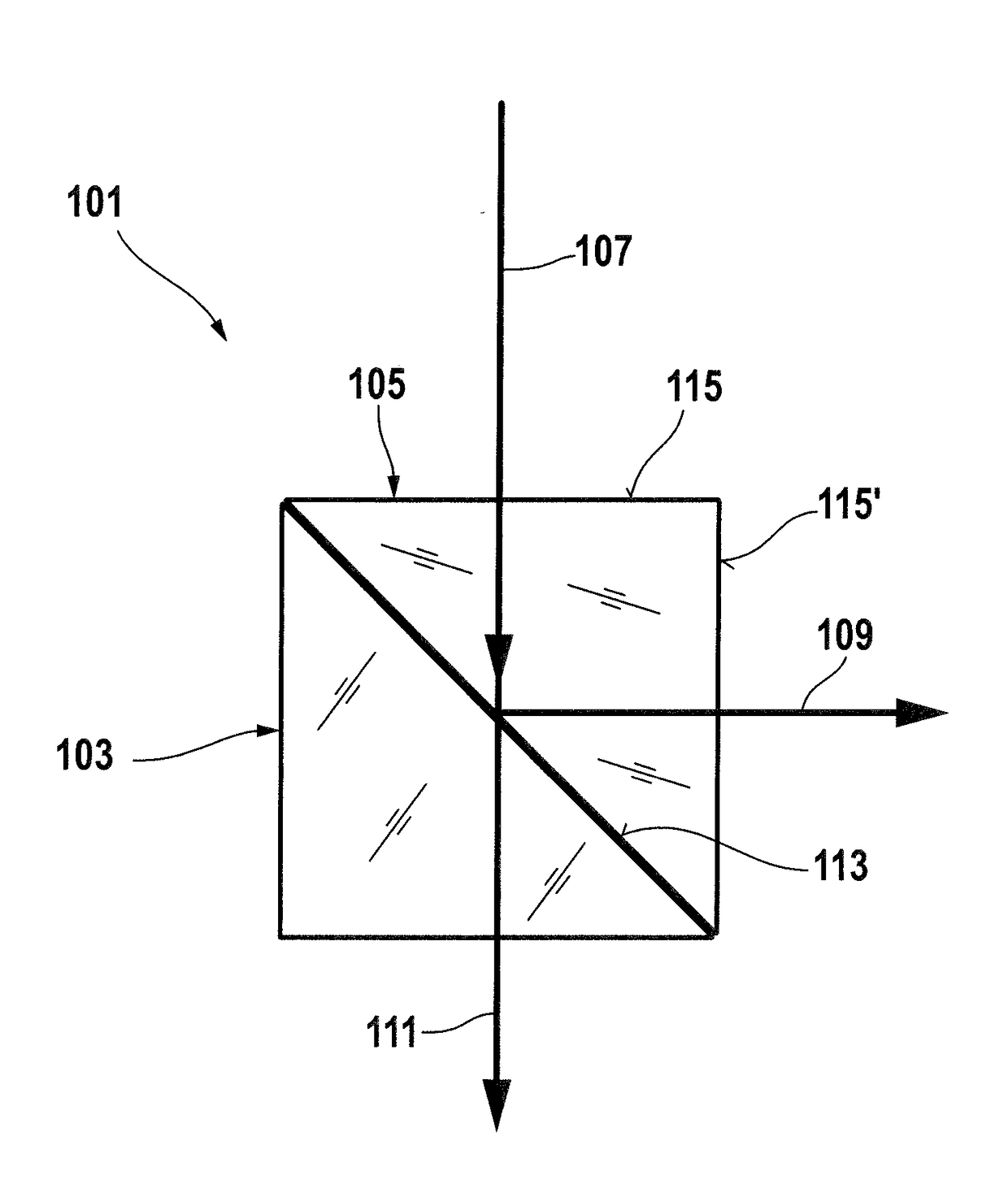
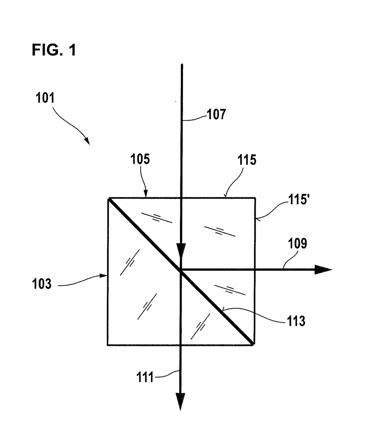
[0034]In FIG. 1, a first beam splitter 101 is schematically represented in side view. It is made up of a first prism 205 and a second prism 103, which have an equilateral triangle as the base area. The second prism 103 has no optical coatings. The first prism 105 has on its side surface 113 an optical coating that serves as a beam splitter layer and under an incident beam 107 transmits light in the visible wavelength range, so that it passes through the prism 103 as a partial beam 111, and reflects light in the infrared wavelength range, so that it is decoupled as a partial beam 109 and leaves the prism 105. Furthermore, the side surfaces 115 and 115′ adjoining the side surface 113 have an optical coating that serves as an antireflection coating, in order that as little intensity as possible is lost when the beam 107 enters through the side surface 115 and the partial beam 109 leaves through the side surface 115′.

[0035]Since the beam splitter layer is thicker by a multiple than a cu...


PUM

PropertyMeasurementUnit
Fractionaaaaaaaaaa
Timeaaaaaaaaaa
Wavelengthaaaaaaaaaa

Abstract

A method for producing an optical element having a main body with a first side surface, which has a first optical coating, and at least one second side surface, which is not plane-parallel to the first side surface and has a second optical coating, is proposed. The method includes the steps of: determining the stress induced in the optical element by the first optical coating of the first side surface; determining a counter-stress, so that the resultant overall stress induced in the optical element is as small as possible; determining the second optical coating while taking into account the determined counter-stress and the optical parameters of the second optical coating; applying the first optical coating on the first side surface; and, applying the second optical coating on the at least one second side surface.

Description

CROSS REFERENCE TO RELATED APPLICATION[0001]This application claims priority of German patent application no. 10 2016 110 351.9, filed Jun. 3, 2016, the entire content of which is incorporated herein by reference.FIELD OF THE INVENTION[0002]The present invention relates to a method for producing an optical element having a main body with a first side surface, which has a first optical coating, and at least one second side surface, which is not plane-parallel to the first side surface and has a second optical coating. It also relates to an optical element produced by this method.BACKGROUND OF THE INVENTION[0003]It is known in the case of optical elements that have an optical coating on their main body that the optical coating can cause compressive or tensile stresses. The thicker the optical coating, and in particular the greater the number of layers of the optical coating, the greater the stress that is caused. These stresses lead to deformations of the main body, which can for exam...

Claims


Application Information

Patent Timeline
IPC IPC(8): G02B1/11G02F1/09G02F1/01G02B1/12H01Q15/00
CPCG02B1/11G02F1/09H01Q15/006G02B1/12G02F1/0102G02B1/10G02B5/04G02B27/0012G02B1/115
Inventor BEDER, CHRISTIANZACZEK, CHRISTOPHGABER, ERWINTONOVA, DIANASUNDERMANN, MICHAEL
Owner CARL ZEISS MEDITEC AG
Learn More