Amorphous carbon, amorphous-carbon coated member, and process for forming amorphous carbon film

Inactive Publication Date: 2005-06-30
TOYOTA CENT RES & DEV LAB INC
View PDF2 Cites 335 Cited by
  • Summary
  • Abstract
  • Description
  • Claims
  • Application Information

AI Technical Summary

Benefits of technology

[0021] The Vickers hardness of the coated film can preferably fall in a range of from 400 or more to 1,500 Hv or less. Thus, not only it is possible to reduce the come-off or damaged coated film, but also to inhibit mating members from being damaged when the surface with the coated film fixed is turned into a sliding surface. Further, the film thickness of the coated film can preferably be from 0.1 or more to 200 μm or less. Sine the elastic modulus of the coated film is low, or since the elastic modulus and hardness thereof are low, the come-off or damaged film occurs less even when the coated film is formed thicker than it is formed usually. Furthermore, the amorphous carbon can preferably comprise silicon in an amount of 50 atomic % or less when the entirety is taken as 100 atomic %. Moreover, a content of carbon can preferably fall in a range of from 10 atomic % or more to 85 atomic % or less.
[0025] forming an amorphous carbon film on at least a part of the substrates by a plasma CVD method. When operating the processing gas pressure and plasma power source so as to overlap negative glows of the neighboring two substrates, a low-voltage and high-current density discharge occurs at the overlapped negative glows. The low-voltage and high-current density discharge can produce soft and less defective amorphous carbon films, because shocks resulting from bombarding ions are less likely to damage films in forming films.

Problems solved by technology

However, high-hardness amorphous carbon films, such as the amorphous carbon film disclosed in the publication, usually exhibit high elastic moduli as well.
Accordingly, when the film thickness of the amorphous carbon film is thickened, the internal stress of the film heightens so that there arises a problem that the film has come off or has been damaged.
In particular, when a hard amorphous carbon film is formed on a substrate of low elastic modulus, the film cannot follow the deformations of the substrate so that the come-off or damaged film has occurred frequently.

Method used


Image

  • Amorphous carbon, amorphous-carbon coated member, and process for forming amorphous carbon film
  • Amorphous carbon, amorphous-carbon coated member, and process for forming amorphous carbon film
  • Amorphous carbon, amorphous-carbon coated member, and process for forming amorphous carbon film

Examples


experimental examples

[0084] Examples of the present amorphous carbon, amorphous-carbon coated member and process for producing an amorphous carbon film will be hereinafter described with reference to the drawings. To begin with, an apparatus for forming an amorphous carbon film will be described.

Film-Forming Apparatus

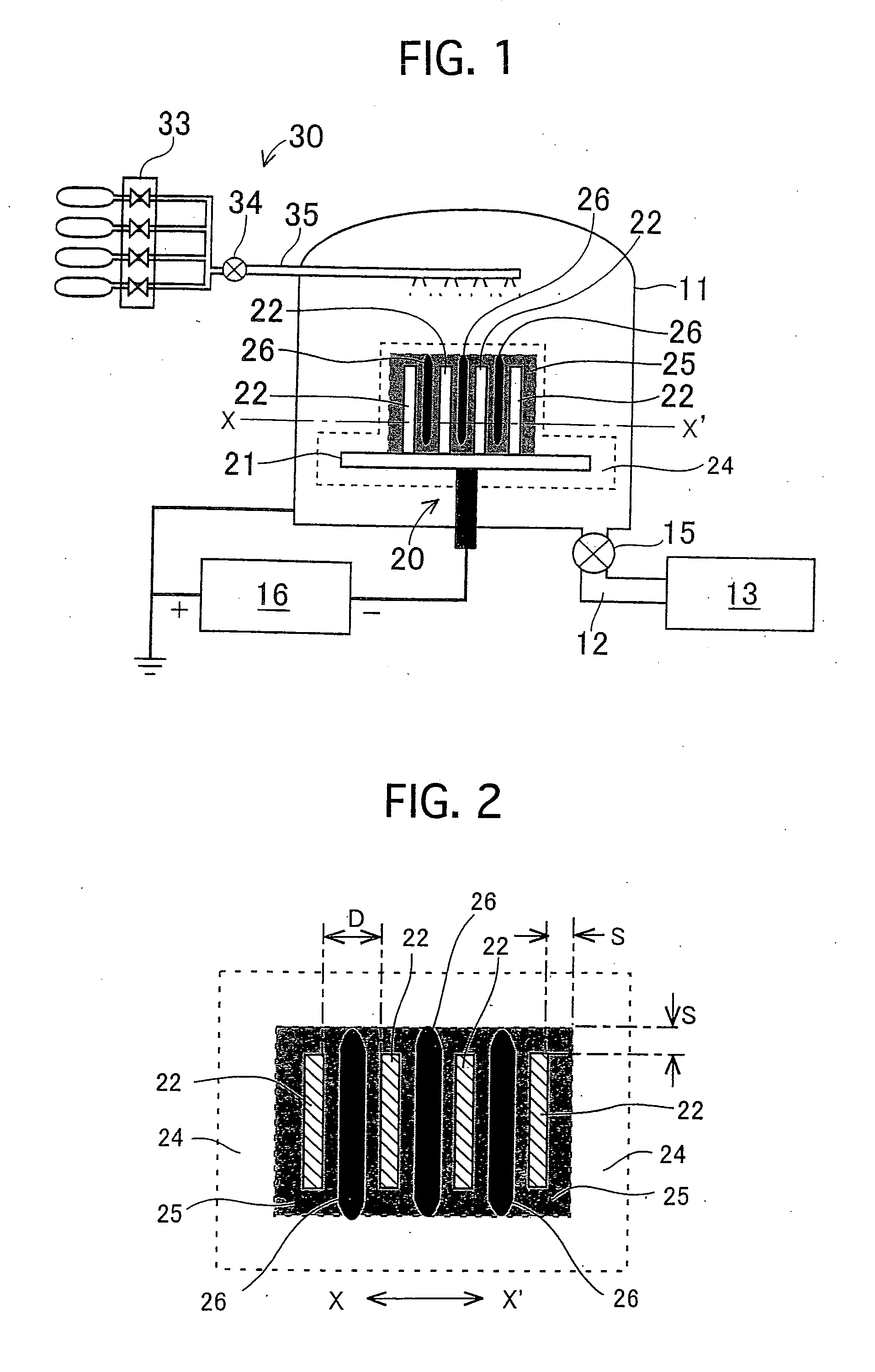
[0085]FIG. 1 and FIG. 5 are conceptual explanatory diagrams on an apparatus for forming an amorphous carbon film, respectively.

[0086] An apparatus for forming an amorphous carbon film comprises a cylinder-shaped stainless-steel chamber 11 used as a film-forming furnace, and an exhaust system 13 communicated with the chamber 11 through an exhaust passage 12. The exhaust system 13 comprises a hydraulic rotary pump, a mechanical booster pump, and a hydraulic diffusion pump. The processing pressure in the chamber 11 is controlled by opening / closing an exhaust control valve 15 disposed in the exhaust passage 12.

[0087] In the chamber 11, there are disposed a negative electrode 20 connected wi...

example no.1

Example No. 1

[0091] An amorphous carbon film according to Example No. 1 will be described using FIG. 1 and FIG. 2. Note that FIG. 2 is a diagram for schematically showing how a glow discharge appeared during forming films in the present example, and is a cross-sectional view taken along the alternate long and one dash line “X”-“X′” of FIG. 1.

[0092] The film-forming apparatus with the above-described construction was operated to form an amorphous carbon film on a surface of the flat plate-shaped substrates 22. In the present example, four pieces of 22 mm×39 mm×3 mm flat plate-shaped substrates made of pure aluminum were used as the flat plate-shaped substrates 22. As illustrated in FIG. 1 and FIG. 2, these flat plate-shaped substrates 22 were disposed one after another so as to be put in a parallel manner in the thickness-wise direction and in a laminated manner. On the top surface of the support bench 21, there were formed grooves (not shown) with a depth of 1 mm so as to dispose t...

example no.2

Example No. 2

[0097] Except that the flat plate-shaped substrates 22 were made of stainless steel (or SUS304), an amorphous carbon film was formed on a surface of the flat plate-shaped substrates 22 in the same manner as Example No. 1. Note that 6-hour film-forming (or a film-forming temperature of 300° C.) produced a 16 μm-film thickness amorphous carbon film on a surface of the flat plate-shaped substrates 22.

[0098] In addition, amorphous-carbon coated members provided with the amorphous carbon film produced in Example No. 2 were labeled No. 2.

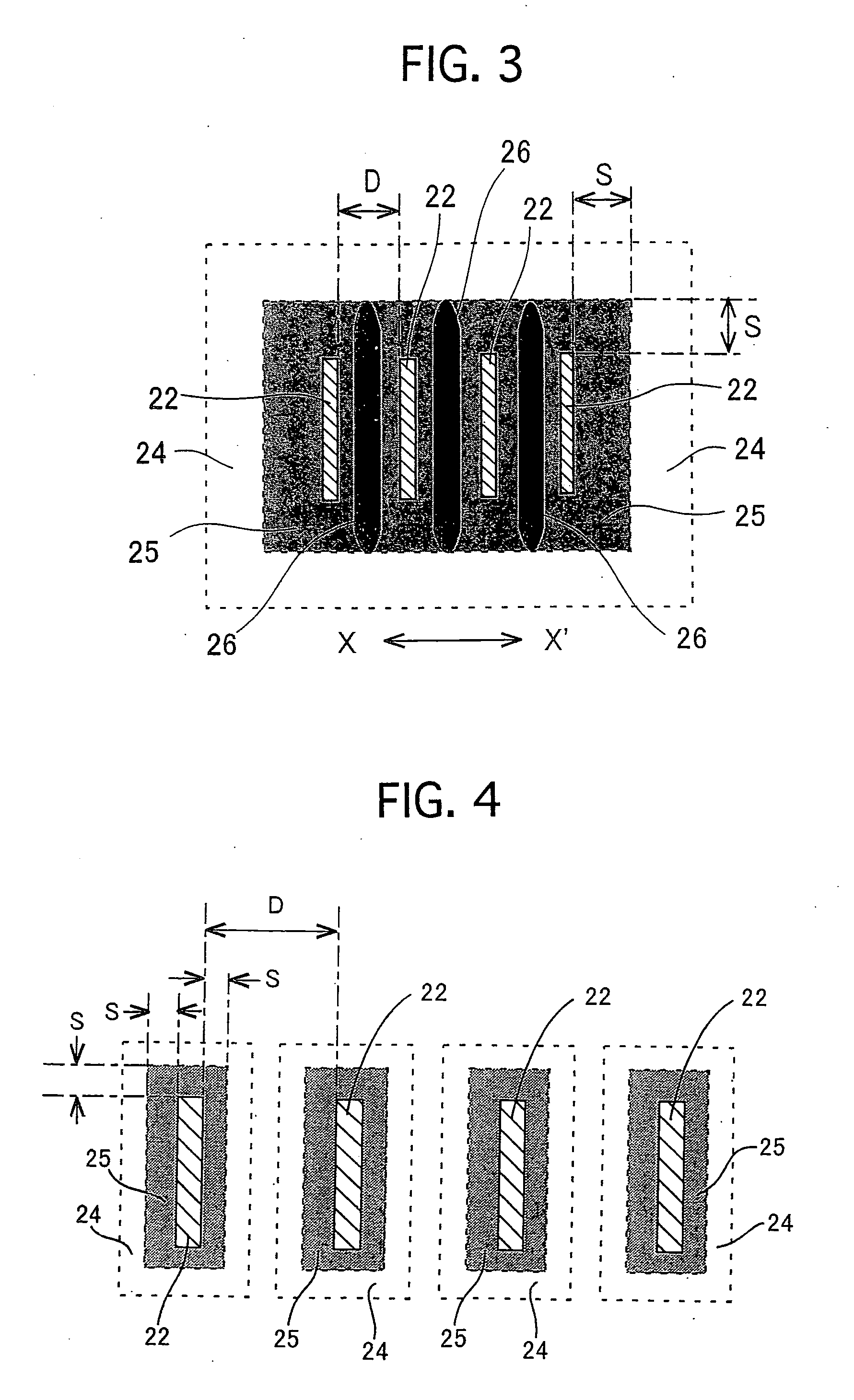
[0099] Here, FIG. 2 illustrates how the glow discharge appeared during film forming in Example Nos. 1 and 2. In Example Nos. 1 and 2, a sheath 25 and a negative glow 24 were formed around the negative electrode 20. On the flat plate-shaped substrates 22, there was formed the sheath 25 provided with a predetermined sheath width (or “S”=5 mm) along the flat-shaped substrates 22. Between the oppositely facing surfaces of the flat plate-shaped ...


PUM

PropertyMeasurementUnit
Thicknessaaaaaaaaaa
Pressureaaaaaaaaaa
Lengthaaaaaaaaaa

Abstract

To provide a soft amorphous carbon exhibiting a low elastic modulus, an amorphous-carbon coated member provided with a coated film comprising the amorphous carbon, and a process for forming an amorphous carbon film. The amorphous carbon comprises carbon as a major component and hydrogen in an amount of from more than 30 atomic % to 60 atomic % or less, and exhibits an elastic modulus of from 40 or more to 150 GPa or less. Moreover, the amorphous-carbon coated member comprises a conductive substrate, and a coated film fixed on at least a part of a surface of the substrate and composed of the amorphous carbon. In addition, in a process for forming the amorphous-carbon coated film, an amorphous carbon film is formed on a surface of conductive substrates by a plasma CVD method. Not only a plurality of the substrates are disposed on a substrate holder, which is disposed in a film-forming furnace and is connected with a negative electrode, in such a state that they face to each other, but also a processing gas pressure and a plasma power source are operated so as to overlap negative glows of the neighboring two substrates.

Description

BACKGROUND OF THE INVENTION [0001] 1. Field of the Invention [0002] The present invention relates to amorphous carbon, an amorphous-carbon coated member using the amorphous carbon, and a process for forming an amorphous carbon film. [0003] 2. Description of the Related Art [0004] Carbon is an extremely good material in view of resource issues and environmental issues, because its deposits are substantially infinite and it is harmless. As for carbon materials, many materials having various crystalline structures, such as diamonds, diamond-like carbon, graphite, fullerenes, carbon nano-tubes, have been known depending on the bonding forms between atoms. Among them, diamond-like carbon (or amorphous carbon) having an amorphous structure is good in terms of mechanical characteristics, such as wear resistance and solid lubricating property so that it is regarded attractive as a functional material having insulative property, visible light / infrared light transmissivity, low dielectric con...

Claims


Application Information

Patent Timeline
IPC IPC(8): C01B31/02B32B9/00C23C16/26H01L21/205H05H1/24
CPCY10T428/30C23C16/26
Inventor NAKANISHI, KAZUYUKIOSHIMA, TADASHIHASEGAWA, HIDEOMORI, HIROYUKIISEKI, TAKASHITACHIKAWA, HIDEOMATSUI, MUNEHISA
Owner TOYOTA CENT RES & DEV LAB INC
Why Eureka
Try Eureka