Method for determining position with improved calibration with opposing sensors

a technology of opposing sensors and determining positions, which is applied in the direction of instruments, surveying, borehole/well accessories, etc., can solve problems such as hysteresis errors, and achieve the effect of improving calibration and accurately detecting

Active Publication Date: 2017-12-14
NORALIS LTD
View PDF0 Cites 10 Cited by
  • Summary
  • Abstract
  • Description
  • Claims
  • Application Information

AI Technical Summary

Benefits of technology

[0040]Embodiments of the present invention include the method and system for determining position with improved calibration. Any device requiring accurate position data can determine location of the device with a sensor calibrated according to the present invention. The location and orientation of the device can be more accurately detected, so that the device can initiate or maintain activity in the desired location and orientation. Furthermore, the position data can be calibrated in real time so that a device can be actively guided, such as navigating a drill bit, while drilling through a rock formation.
[0042]The step of generating the position value further comprises generating an adjusted plastic bias value to set the position value, so that the position value accounts for bias and hysteresis errors and improves accuracy of the position value. The plastic bias value relates the temperature data signal, the duration of the temperature, and the position data signals, according to bias and hysteresis of the oscillation element of the position sensor. There is additional error correction based on the differences between the first position data signal and the second position data signal due to gravity. The method accounts for the bias error of the component of each position sensor, relative to temperature, the hysteresis error of the component of each position sensor, relative to duration of temperature, and the orientation of the gravitation field. The adjusted plastic bias value can at least partially cancel out hysteresis errors and other errors due to the electronics, physics and chemistry of the sensing element. Additionally, the adjusted plastic bias value correction to the position value is a continual temporal additional correction to the original sensor bias calibration factor. Note the plastic bias correction is applied to each one of the opposing sensors. In the present invention, the position data signals can be corrected so that measurements of gravity on the oscillation element and capacitance (open loop) or currents (closed loop) of the position sensors are corrected to the set position value.
[0044]Embodiments of the system of the present invention include the first position sensor, the second position sensor, the temperature sensor, processor module, memory module and terminal device. The terminal device can be any device requiring position data for operation, such as a downhole tool in the oil and gas industry, a survey tool for mapping locations, or a mobile probe for tracking location of the sensor or a video game controller for translating movements into game action. The present invention can include any terminal device that uses location and orientation data. In some embodiments, the position sensors can be MMS sensors exposed to high temperatures. The system can also include another pair of position sensors generating another pair of position data signals and another position value adjusted according to another adjusted plastic bias value. The multiple sensor pair embodiment can further reduce errors and confirm accuracy of location and orientation. The system can also include at least one magnetometer in proximity to the temperature sensor. The field data signals from the magnetometer can be used to determine calculated parameters, such as compass azimuth and the earth's magnetic dip. These parameters use both the field data signals as magnetometer magnetic signals and position data signals as accelerometer gravitational signals, such that these parameters can also be improved with the plastic bias value of the present invention.

Problems solved by technology

The method accounts for the bias error of the component of each position sensor, relative to temperature, the hysteresis error of the component of each position sensor, relative to duration of temperature, and the orientation of the gravitation field.

Method used


Image

  • Method for determining position with improved calibration  with opposing sensors
  • Method for determining position with improved calibration  with opposing sensors
  • Method for determining position with improved calibration  with opposing sensors

Examples


Embodiment Construction

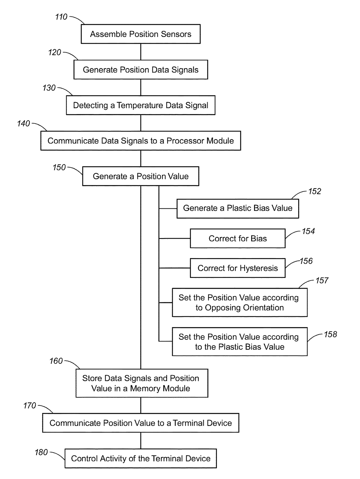
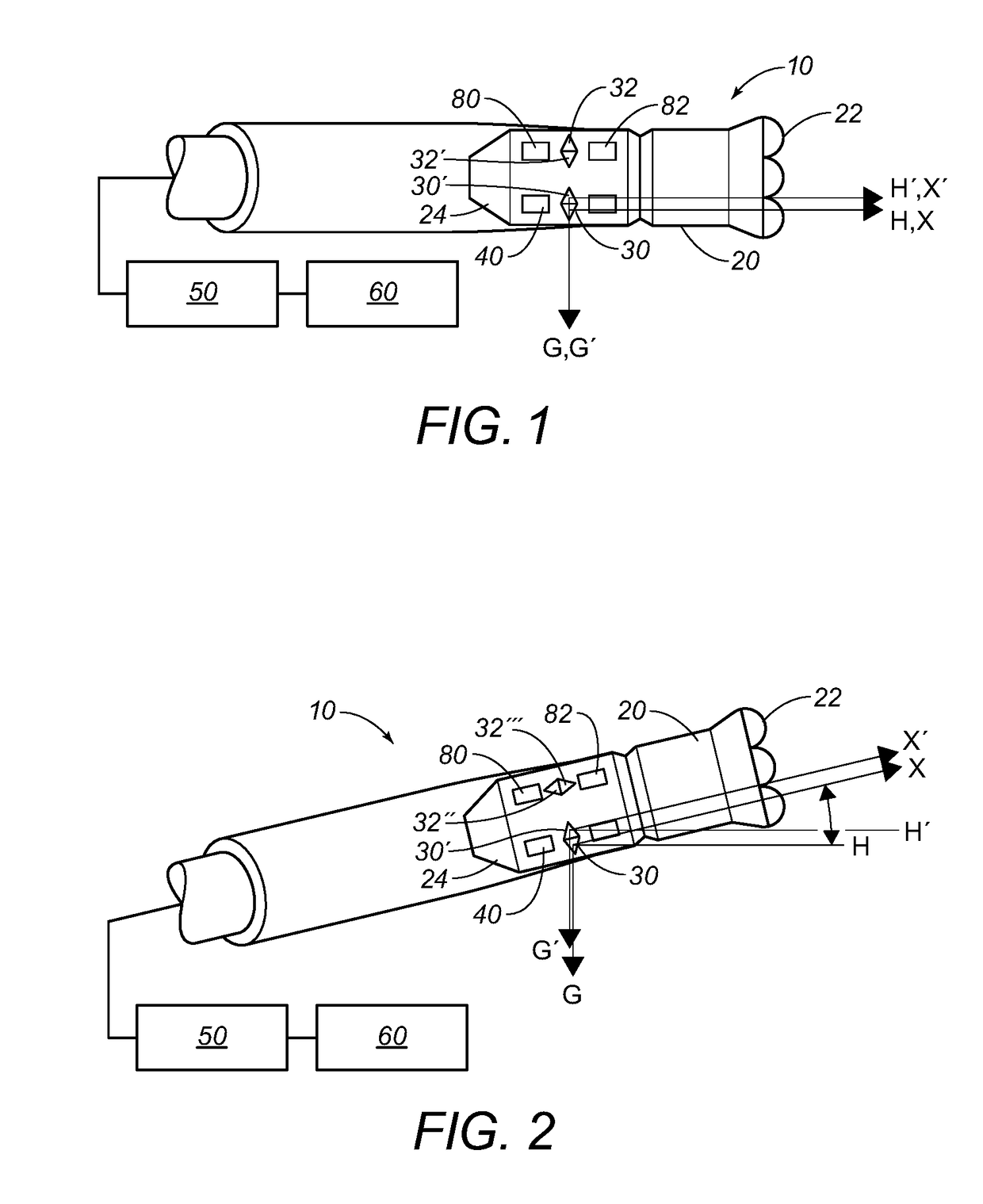
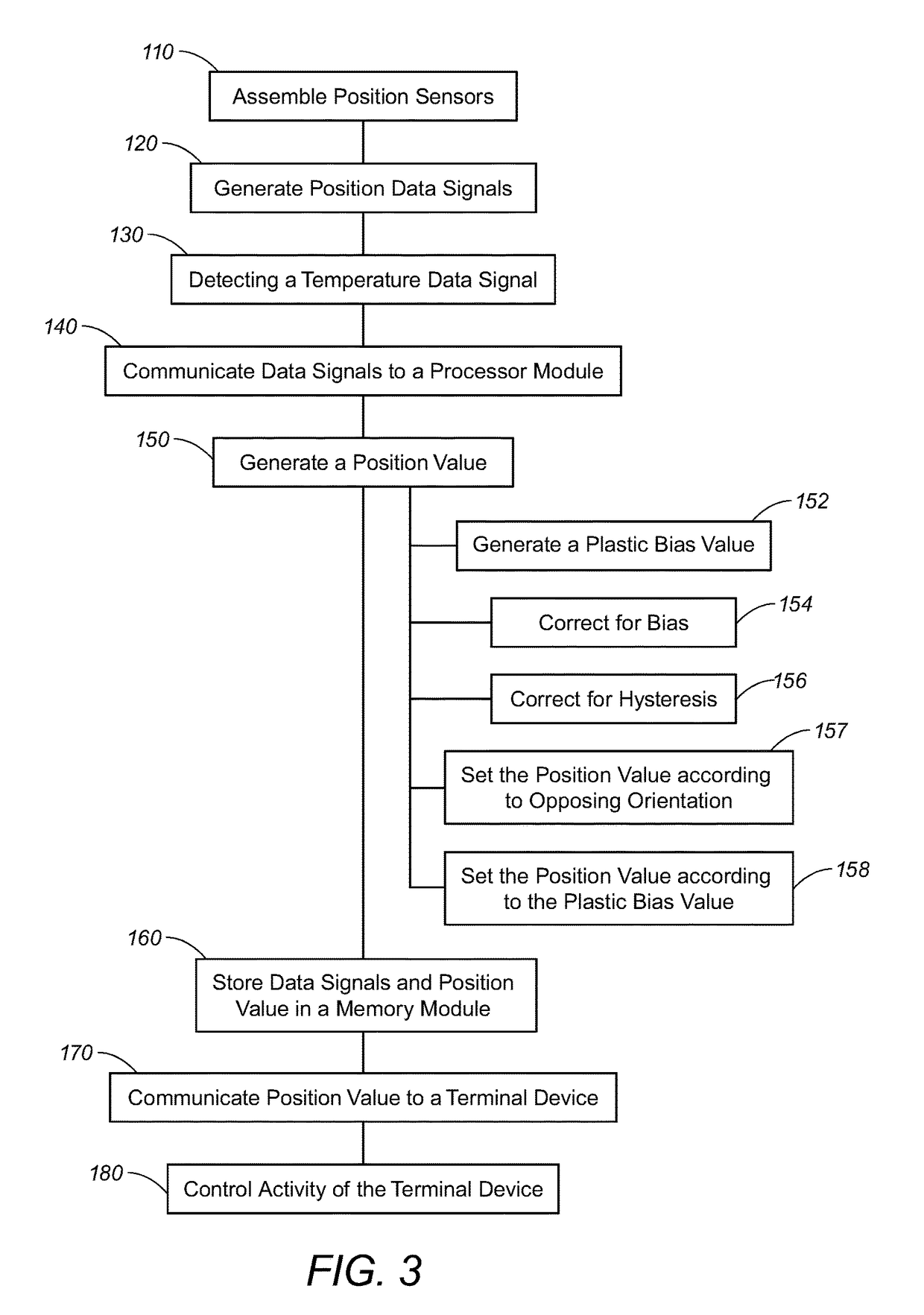
[0048]Referring to FIG. 1-3, the present invention includes the method and system 10 for determining position of a device 20 with improved calibration of a first position sensor 30 and a second position sensor 30′ of the device. The location and orientation of the device 20 are more accurate with the present invention. The position sensors 30, 30′ calibrated according to the present invention allow the device 20 to properly initiate or maintain activity in the intended location and orientation. When calibrated in real time, the device 20 can be actively guided, such as navigating a drill bit 22, while drilling through a rock formation. Errors due to bias and hysteresis can be reduced by the method and system of the present invention. Previous sensors with large bias and hysteresis errors, such as MMS sensors exposed to high temperatures, in particular open loop devices, can now be incorporated into devices for reliable determination of position data. Errors due to gravity and a grav...


PUM


Abstract

The method and system for determining position with improved calibration allows a device to initiate activity at the proper location, such as navigating a drill bit through a rock formation. A pair of position sensors in opposite orientations generates position data signals. A temperature sensor detects temperature and duration of the temperature. An adjusted plastic bias value is determined by a processor module based on the temperature data signal, the duration of the temperature, and the position data signals so as to account for bias and hysteresis errors and error correction based on the opposing orientations of the pair of position sensors. A position value is set according to the adjusted plastic bias value so that the position value is more accurate. The activity of the terminal device is initiated or maintained according to the position value calibrated by the adjusted plastic bias value.

Description

CROSS-REFERENCE TO RELATED APPLICATIONS[0001]See also Application Data Sheet.STATEMENT REGARDING FEDERALLY SPONSORED RESEARCH OR DEVELOPMENT[0002]Not applicable.THE NAMES OF PARTIES TO A JOINT RESEARCH AGREEMENT[0003]Not applicable.INCORPORATION-BY-REFERENCE OF MATERIAL SUBMITTED ON A COMPACT DISC OR AS A TEXT FILE VIA THE OFFICE ELECTRONIC FILING SYSTEM (EFS-WEB)[0004]Not applicable.STATEMENT REGARDING PRIOR DISCLOSURES BY THE INVENTOR OR A JOINT INVENTOR[0005]Not applicable.BACKGROUND OF THE INVENTION1. Field of the Invention[0006]The present invention relates to determining position of a tool for operations at a location of the tool. In particular, the present invention relates to calibrating sensors for determining position of the sensors. Even more particularly, the present invention relates to calibrating sensors on a downhole tool to more accurately determine position of the downhole tool in an underground formation, such that setting location of activity or operations, such ...

Claims


Application Information

Patent Timeline
Patent Type & Authority Applications(United States)
IPC IPC(8): E21B44/00G01P1/00E21B47/06G01P21/00E21B47/024E21B7/04
CPCE21B44/00G01P21/00E21B47/065E21B7/04E21B47/024G01P1/006G01P15/132G01P2015/0828E21B47/07
Inventor CLOSE, DAVIDTROY, GEORGE W.
Owner NORALIS LTD
Why Eureka
Try Eureka