
X-Ray Scanning System

a scanning system and x-ray technology, applied in the field of x-ray scanning system, can solve the problems of limiting the range of end-point x-ray energies that can reasonably be used, increasing increasing so as to increase system complexity and cost, increase thickness, and increase the effect of system weight and chopper wheel moment of inertia

Active Publication Date: 2017-12-14
VIKEN DETECTION CORP
View PDF11 Cites 22 Cited by
  • Summary
  • Abstract
  • Description
  • Claims
  • Application Information

AI Technical Summary

Benefits of technology

The patent text describes a new technology for improving the detection of x-rays, particularly in the BX imaging mode. The technology solves problems related to the need for a thick material (tungsten or lead) to create the pencil beams for BX imaging, which leads to increased weight, system complexity, and cost. The technology also allows for the detection of backscattered x-rays without the need for bulky detectors that need to be concealed or stored in an external enclosure. Finally, the technology expands the range of x-ray energies that can be used for detection.

Problems solved by technology

This required increase in thickness leads to greater system weight and chopper wheel moment of inertia, with related increases in system complexity and cost.
These factors effectively limit the range of end-point x-ray energies that can reasonably be used.
Moreover, in relation to detection of backscattered x-rays, prior-art, box-type, backscatter detectors are bulky and cannot therefore be easily mounted to the exterior of a vehicle for mobile imaging systems, particularly if the system needs to be used covertly.

Method used


Image

  • X-Ray Scanning System
  • X-Ray Scanning System
  • X-Ray Scanning System

Examples


Embodiment Construction

[0036]A description of example embodiments of the invention follows.

[0037]Rotating disks were used in the earliest x-ray imaging systems designed in 1972. Initially, the rotating disk was used to create a digital transmission x-ray imaging system. Backscatter imaging was eventually added by incorporating additional scatter detectors in the back direction. Backscatter imaging using chopper disks has been used since the 1980's to create scanning beams of x-rays with end-point energies in the 120 keV to 160 keV range. The method has not been practical at much higher energies because the needed thickness (and therefore weight) of the rotating disk increase rapidly with energy.

[0038]Disclosed herein are embodiment x-ray scanning systems that can be extended to operate at much higher x-ray energies of at least 500 keV while controlling thickness and weight of chopper disks.

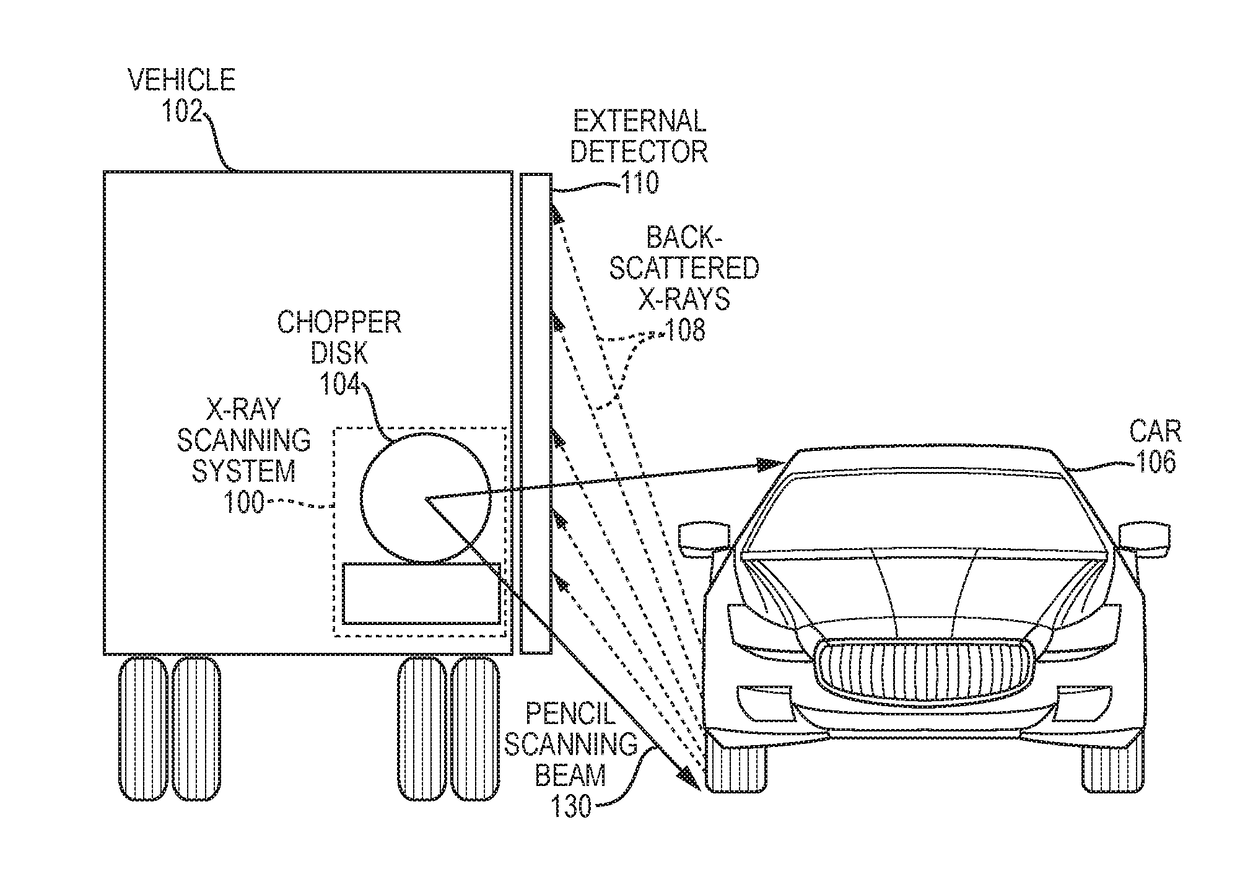
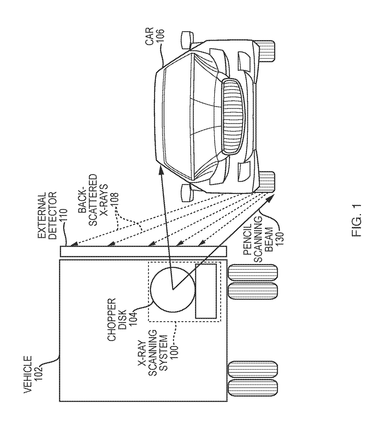
[0039]FIG. 1 is a schematic diagram illustrating an embodiment x-ray scanning system 100 mounted within a vehicle 102...


PUM


Abstract

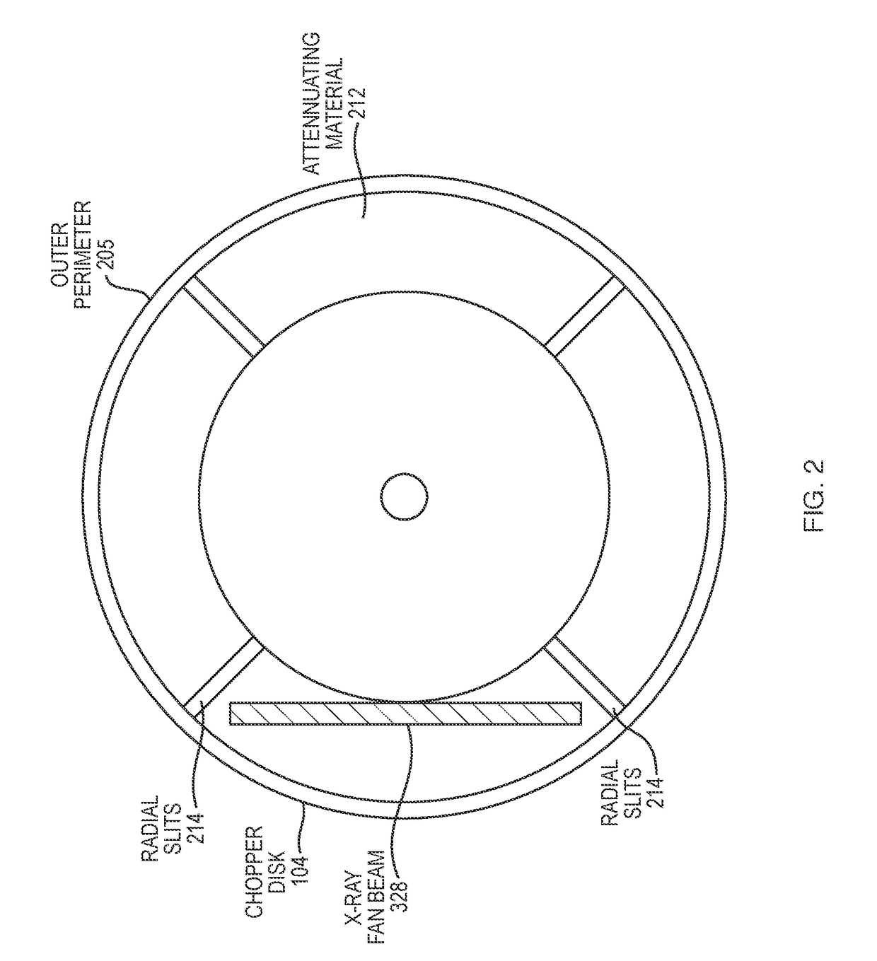
An x-ray scanning system includes an x-ray source that produces a collimated fan beam of incident x-ray radiation. The system also includes a chopper wheel that can be irradiated by the collimated fan beam. The chopper wheel is oriented with a wheel plane containing the chopper wheel substantially non-perpendicular relative to a beam plane containing the collimated fan beam. In various embodiments, a disk chopper wheel's effective thickness is increased, allowing x-ray scanning with end point energies of hundreds of keV using relatively thinner, lighter, and less costly chopper wheel disks. Backscatter detectors can be mounted to an exterior surface of a vehicle housing the x-ray source, and slits in the disk chopper wheel can be tapered for more uniform target irradiation.

Description

RELATED APPLICATIONS[0001]This Application claims the benefit of U.S. Provisional Application No. 62 / 084,222, filed on Nov. 25, 2014 and U.S. Provisional Application No. 62 / 082,321, filed on Nov. 20, 2014. The entire teachings of the above Applications are incorporated herein by reference.BACKGROUND[0002]X-ray backscatter (BX) imaging has been used since the 1980's for detecting concealed contraband, such as drugs, explosives, and weapons. The BX imaging technique differs in fundamental ways from the traditional transmission (TX) x-ray method of searching for contraband. The TX method works by creating an image of the x-rays that are transmitted through the target. Transmission images are created by a fan or cone beam of x-rays that pass through the target to a pixelated x-ray detector. The size of the individual detector elements determines the pixel resolution in the transmission image.[0003]In contrast to TX images, backscatter images are created by scanning the target with a pen...

Claims


Application Information

Patent Timeline
Patent Type & Authority Applications(United States)
IPC IPC(8): G21K1/04G01V5/00
CPCG21K1/043G01V5/0041G01V5/0025G01V5/222G01V5/224
Inventor ROTHSCHILD, PETER JOHN
Owner VIKEN DETECTION CORP
Learn More