Automatic target recognition and dispensing system

Active Publication Date: 2017-12-21
AGERRIS PTY LTD
View PDF9 Cites 84 Cited by
  • Summary
  • Abstract
  • Description
  • Claims
  • Application Information

AI Technical Summary

Benefits of technology

[0060]In some embodiments the sensing system is mounted (e.g. on a boom pole or similar, and optionally telescopically extensible) so as to be spaced from the shooting system (e.g. nozzles, actuators) by a predetermined distance to allow for increased computation time by the sensing, classification, and/or control systems of the apparatus. For example, if a vehicle is travelling over a crop at a specified velocity (e.g. 1 m/s) such that the total time taken from image acquisition to target identification and localisation is 1 second, then ideally the sensing system would be positioned 1 metre ahead of the shooting system whereby the shooting system is better positioned at the time of actuation. In other embodiments, the images, sensing data and target identification requirements can be communicated to remote computers (e.g. over network to supercomputers

Problems solved by technology

However, the distribution is substantially untargeted and as a result, the process is relatively inefficient and the resultant water consumption is relatively high.
However, the infrastructure is costly to install and maintain, and water consumption on commercial scale agriculture is still relatively high.
Again, however, because these application systems are relatively untargeted, large quantities of fertilisers or pesticides are required and a significant proportion is inevitably wasted.
Aside from the significant cost resulting from this wastage, the environmental effects may be negative, for example if potentially toxic airborne pesticides are inadvertently blown

Method used


Image

  • Automatic target recognition and dispensing system
  • Automatic target recognition and dispensing system
  • Automatic target recognition and dispensing system

Examples


first embodiment

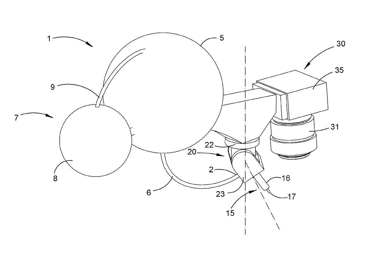
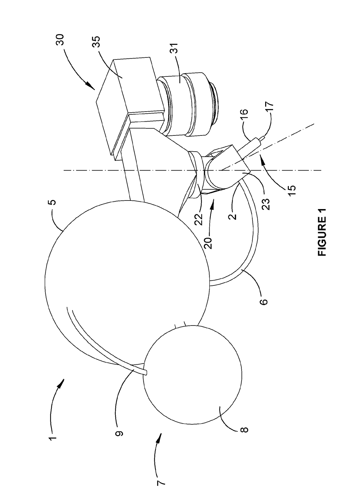
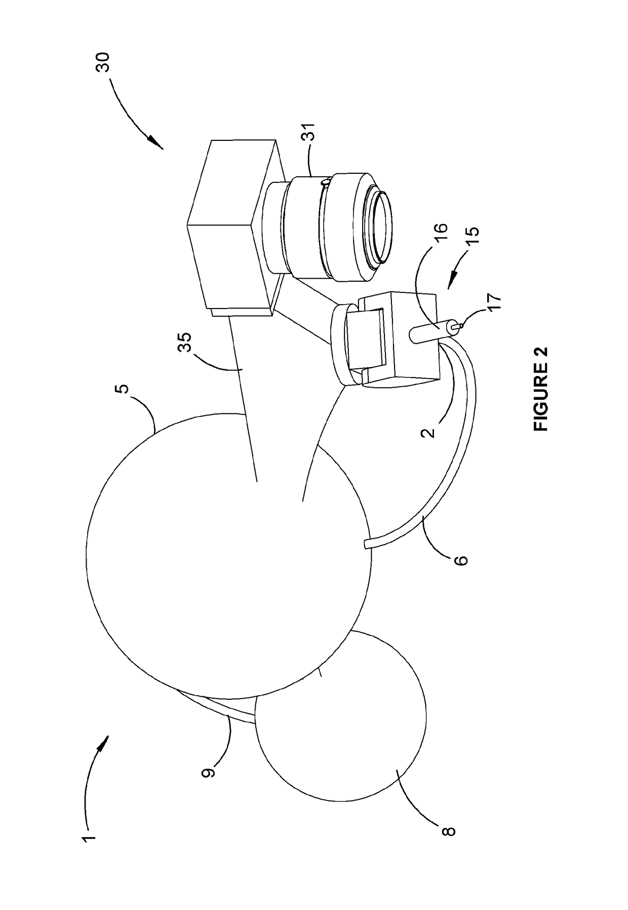
[0109]Referring initially to FIGS. 1 and 2, the invention in a first embodiment provides an apparatus (1) for projecting a fluid, preferably a liquid, toward a target. The apparatus includes a fluid inlet (2) adapted for connection to a source of pressurised fluid selected for use in connection with a specific environmental control function such as irrigation, fertilisation, pest eradication, weeding, pruning, thinning, planting or harvesting, as described in more detail below.

[0110]In this embodiment, the source of fluid is a generally spherical fluid storage reservoir (5) connected to the fluid inlet by means of a supply line (6), and also connected to an associated fluid pressurisation system (7). In this embodiment, the pressurisation system includes a spherical pressure vessel (8) adapted for periodic re-pressurisation to a predetermined operational pressure level. The pressure vessel (8) is connected for fluid communication with the reservoir (5) by means of high pressure supp...

second embodiment

[0129]FIGS. 3 and 4 show the invention, in which corresponding features are denoted by like reference numerals. In this case, an external pump assembly (38) is used to generate the supply pressure for the control liquid and in variations of this embodiment, the liquid storage reservoir (5) incorporates an internal pump assembly to generate the supply pressure. A first servomotor (40) is used to effect rotation of the first member (22) of the outlet support assembly about the first axis, while a second servomotor (42) is used to effect rotation of the second member (23) of the outlet support assembly about the second axis. The dispensing valve is positioned at, or closely adjacent, the point of intersection of the rotational control axes, which minimises the swept volume of the end-effector and reduces the transformation calculations required by the control system. This configuration of servomotors also enables the liquid dispensing valve to be positioned closely adjacent to, or in c...


PUM


Abstract

An automated apparatus, method and system for projecting a control agent toward a recognised target for the purposes of agricultural cultivation or environmental management or various other applications; a source of the control agent adapted for use in connection with an environmental control function, an outlet incorporating at least one outlet orifice to direct the control agent emanating from the outlet orifice toward a target. An activation means is movable between an operative mode and an inoperative mode in which the outlet is effectively closed. A targeting mechanism movable on at least one independent control axis provided for selectively orienting the outlet orifice and thereby orienting the control agent in the operative mode. A first sensing system, a classification system, a control system in accordance with a predetermined control logic adapted to deliver doses of the control agent to the identified targets for the purposes of the environmental control function.

Description

FIELD OF THE INVENTION[0001]The present invention primarily relates to an automated apparatus, method and system for projecting a fluid jet or other control agent toward a recognised target, for the purposes of agricultural cultivation or environmental management.[0002]The invention has been developed primarily for use in the targeted application of irrigation liquids or fertilisers to crops and / or the targeted application of pesticides to weeds, insects or other pests. The invention will be described predominantly in these contexts. It should be appreciated, however, that the invention is not limited to these particular applications, being potentially also adaptable for crop planting, pruning, harvesting, weeding and other analogous purposes. It should also be appreciated that the present invention is also adaptable for a variety of applications other than for agricultural purposes.BACKGROUND OF THE INVENTION[0003]The following discussion of the prior art is intended to place the i...

Claims


Application Information

Patent Timeline
IPC IPC(8): A01B79/00A01M7/00A01M21/04
CPCA01B79/005A01M7/0089A01M7/006A01M21/043A62C37/40A01G25/09B64D1/18B64C39/024B64D47/08B64U2101/30B64U2101/00
Inventor CALLEIJA, MARKSUKKARIEH, SALAH
Owner AGERRIS PTY LTD
Why Eureka
Try Eureka