Supercharge Your Innovation With Domain-Expert AI Agents!

Overcurrent protection circuit

a protection circuit and overcurrent technology, applied in the direction of electronic switching, emergency protection arrangements for limiting excess voltage/current, pulse technique, etc., can solve the problems of overcurrent protection circuit, short circuit between the upper switching element and the lower switching element, and possible destruction of the switching elemen

Active Publication Date: 2017-12-21
JTEKT CORP
View PDF4 Cites 9 Cited by
  • Summary
  • Abstract
  • Description
  • Claims
  • Application Information

AI Technical Summary

Benefits of technology

The invention provides an overcurrent protection circuit that can detect if there is a low fixing failure in an amplification circuit used for through-current detection. This is important because the circuit can prevent damage from overcurrent situations. The circuit uses a shunt resistor to create an electronic circuit that monitors the voltage across a resistor and compares it to a reference voltage. When there is no low fixing failure, the output voltage from the amplification circuit is higher than the reference voltage. On the other hand, if there is a low fixing failure, the output voltage from the amplification circuit is lower than the reference voltage. This allows for easy detection of any problems with the amplification circuit.

Problems solved by technology

In an electronic circuit such as an inverter circuit which includes a series circuit of an upper switching element and a lower switching element, the switching elements or the electronic circuit may fail, leading to a short circuit between the upper switching element and the lower switching element.
When an excessive through-current flows through the switching elements, the switching elements may be destroyed.
However, the overcurrent protection circuit described in JP 2007-74794 A described above is disadvantageous when, for example, a low fixing failure (a failure in which an amplifier output is fixed to a ground level) occurs in the amplifier included in the first comparator.
Thus, the electronic circuit starts operating with the failure undetected.

Method used


Image

  • Overcurrent protection circuit
  • Overcurrent protection circuit
  • Overcurrent protection circuit

Examples


Embodiment Construction

[0012]An embodiment of the invention will be described below in detail with reference to the attached drawings.

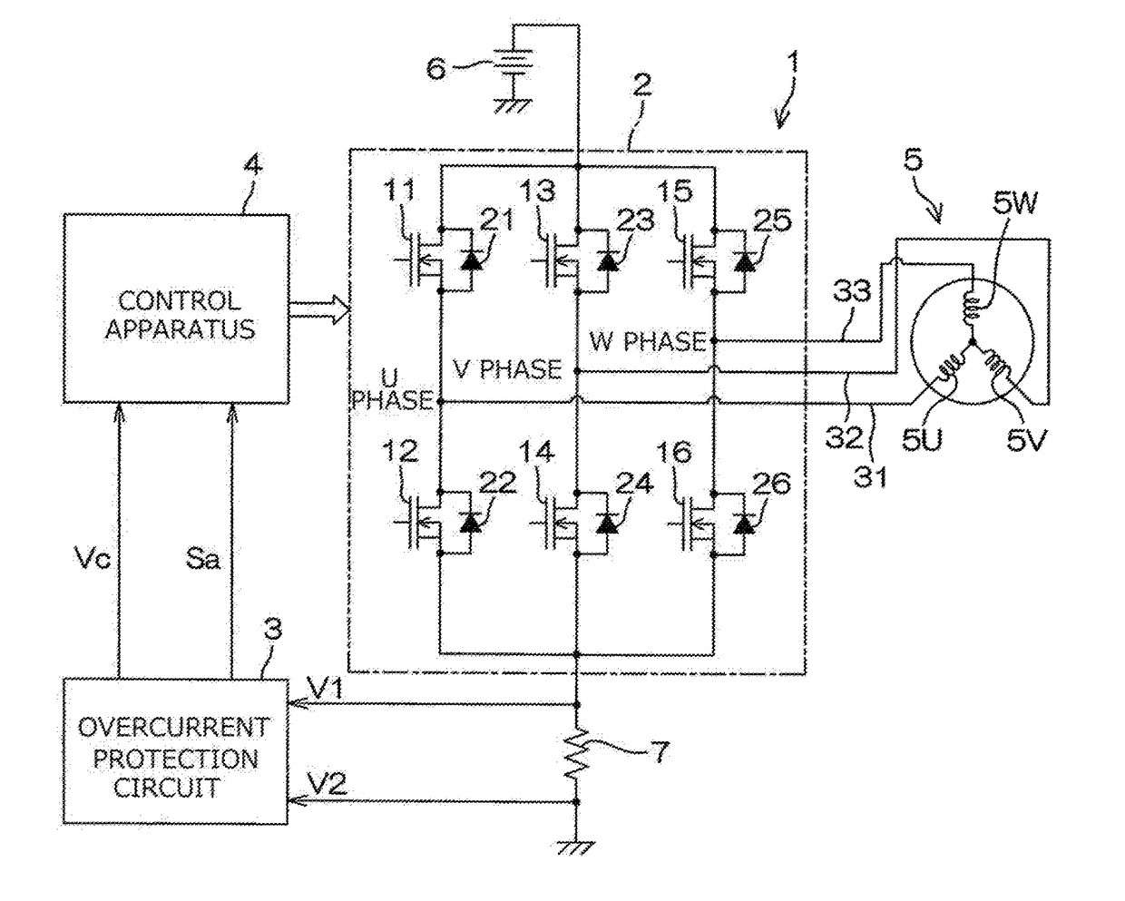
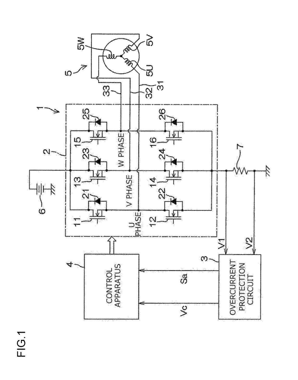
[0013]FIG. 1 is a schematic diagram illustrating a general configuration of a motor driving control apparatus including a three-phase inverter circuit to which an overcurrent protection circuit according to an embodiment of the invention is applied.

[0014]A motor driving control apparatus 1 includes a three-phase inverter circuit 2, an overcurrent protection circuit 3, and a control apparatus 4. The motor driving control apparatus 1 may be configured, for example, to controllably drive an electric motor for electric power steering systems.

[0015]The three-phase inverter circuit 2 supplies power to an electric motor 5 and is controlled by the control apparatus 4. The three-phase inverter circuit 2 includes a series circuit of a pair of switching elements 11, 12 corresponding to a U phase of the electric motor 5, a series circuit of a pair of switching elements 13, 14 correspon...


PUM


Abstract

An overcurrent protection circuit includes an amplifier configured to amplify an inter-terminal voltage of a shunt resistor, an offset application circuit configured to allow the amplifier to provide an output with a predetermined offset voltage additionally applied thereto, a first comparator that compares an output voltage from the amplifier with a predetermined first reference voltage higher than the offset voltage to output a through-current sensing signal when the output voltage from the amplifier is higher than a first reference voltage, and an amplifier failure determination circuit that compares the output voltage from the amplifier with a predetermined second reference voltage that is higher than zero and lower than the offset voltage to output an amplification circuit failure determination signal corresponding to a result of the comparison.

Description

INCORPORATION BY REFERENCE[0001]The disclosure of Japanese Patent Application No. 2016-121959 filed on Jun. 20, 2016 including the specification, drawings and abstract, is incorporated herein by reference in its entirety.BACKGROUND OF THE INVENTION1. Field of the Invention[0002]The invention relates to an overcurrent protection circuit used for an electronic circuit having at least one series circuit of an upper switching element and a lower switching element.2. Description of the Related Art[0003]In an electronic circuit such as an inverter circuit which includes a series circuit of an upper switching element and a lower switching element, the switching elements or the electronic circuit may fail, leading to a short circuit between the upper switching element and the lower switching element. When such a short circuit occurs, a through-current flows from a power supply through the upper switching element and the lower switching element to ground. When an excessive through-current fl...

Claims


Application Information

Patent Timeline
Patent Type & Authority Applications(United States)
IPC IPC(8): H02H9/02H02H5/04H02H3/00H02H3/08H03K17/08H02M1/32
CPCH02H9/02H02M1/32H02H3/006H03K17/08H02H5/041H02H3/08H02H3/044H02H7/1255H03K17/0822H03K17/0828
Inventor KITAMOTO, HIROSHIUCHIDA, NOBUHIRO
Owner JTEKT CORP
Features
  • R&D
  • Intellectual Property
  • Life Sciences
  • Materials
  • Tech Scout
  • Unparalleled Data Quality
  • Higher Quality Content
  • 60% Fewer Hallucinations
Learn More