Method for operating a coordinate measuring machine

a technology of coordinate measuring machine and measuring device, which is applied in the field of precision metrology, can solve the problems of inability to adjust such parameters and/or compensate for such frequently changing timing deviations in a flexible and easy-to-use manner, host system may also lack a signal line and/or data transmission protocol, etc., and achieves the effect of convenient us

Active Publication Date: 2017-12-28
MITUTOYO CORP
View PDF0 Cites 11 Cited by
  • Summary
  • Abstract
  • Description
  • Claims
  • Application Information

AI Technical Summary

Benefits of technology

[0014]This summary is provided to introduce a selection of concepts in a simplified form that are further described below in the Detailed Description. This summary is not intended to identify key features of the claimed subject matter, nor is it intended to be used as an aid in determining the scope of the claimed subject matter.
[0015]Scanning probes that include local signal processing (which may be characterized as “smart probes”), may include adjustable noise filters and/or measurement averaging or the like, provided in the probe. Related parameters may be adjusted by program instructions that are used to control the CMM and/or the probe. The parameters may be changed (e.g., downloaded to the probe) at any time during the execution of an inspection routine for a workpiece, depending on the required accuracy for measuring a particular feature, for example. When such parameters are changed, the delays or timing deviations outlined previously are inherently affected. In general, it may be desired to retrofit such smart prob...

Problems solved by technology

When such parameters are changed, the delays or timing deviations outlined previously are inherently affected.
In general, it may be desired to retrofit such smart probes onto older host systems that did not anticipate the smart probe features, and therefore lack the capability of adjusting such...

Method used


Image

  • Method for operating a coordinate measuring machine
  • Method for operating a coordinate measuring machine
  • Method for operating a coordinate measuring machine

Examples


Embodiment Construction

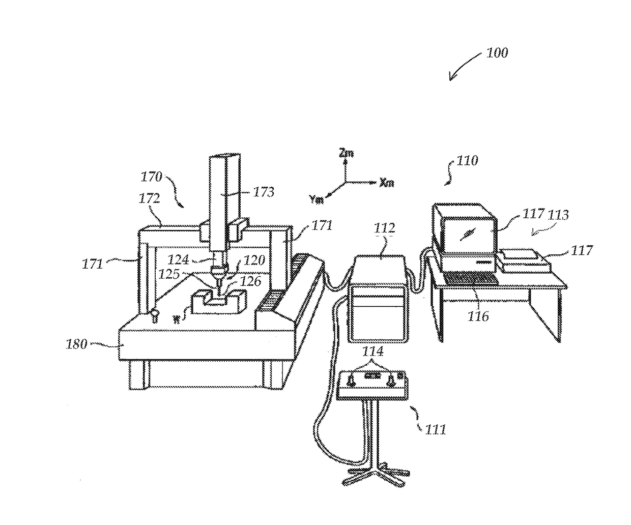
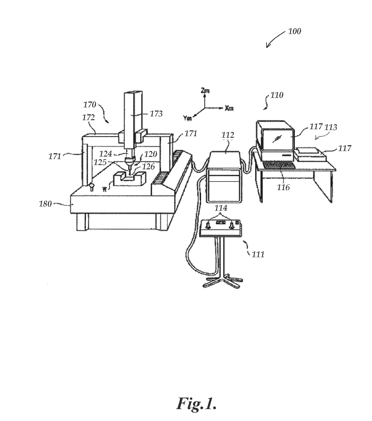
[0025]FIG. 1 is a diagram showing various typical components of a CMM 100. The CMM 100 includes a CMM control system 110, and a surface scanning probe 120. The CMM control system 110 includes an operating unit 111, a motion controller 112 that controls movements of the CMM 100, and a host computer 113. The operating unit 111 is coupled to the motion controller 112 and may include joysticks 114 for manually operating the CMM 100. The host computer 113 is coupled to the motion controller 112 and operates the CMM 100 and processes measurement data for a workpiece W. The host computer 113 includes input means 116 (e.g., a keyboard, etc.) for inputting, for example, measurement conditions, and output means 117 (e.g., a display, printer, etc.) for outputting, for example, measurement results.

[0026]The CMM 100 includes a drive mechanism 170 which is located on a surface plate 180, and an attachment portion 124 for attaching the scanning probe 120 to the drive mechanism 170. The drive mecha...


PUM


Abstract

A method is disclosed for operating a coordinate measuring machine (CMM) including a workpiece scanning probe. The method provides two different measurement sampling period durations in the scanning probe: a first shorter sampling duration provides a faster measurement having a first accuracy, a second longer sampling duration provides a slower measurement having a second (better) accuracy. The shorter sampling duration may be repeatedly interleaved or alternated with the longer sampling duration to provide sufficient accuracy and response time for motion control purposes during ongoing operation of the CMM. The longer sampling duration may provide high accuracy probe measurements to combine with position coordinate values from encoders located on motion axes of the CMM (outside the scanning probe) to provide high accuracy workpiece measurements at a desired frequency, or upon demand. A probe measurement timing subsystem may determine initiation times of the first and second sampling durations.

Description

CROSS-REFERENCE TO RELATED APPLICATION(S)[0001]This application is a continuation-in-part of U.S. patent application Ser. No. 15 / 192,799, entitled “METHOD FOR OPERATING A COORDINATE MEASURING MACHINE,” filed Jun. 24, 2016, the disclosure of which is hereby incorporated herein by reference in its entirety.BACKGROUNDTechnical Field[0002]This disclosure relates to precision metrology, and more particularly to signals in probes used with coordinate measuring machines.Description of the Related Art[0003]Coordinate measuring machines (CMMs) can obtain measurements of inspected workpieces. One exemplary prior art CMM described in U.S. Pat. No. 8,438,746 (the '746 patent), which is hereby incorporated herein by reference in its entirety, includes a probe for measuring a workpiece, a movement mechanism for moving the probe, and a controller for controlling the movement. CMMs employing mechanical contact probes are also described in U.S. Pat. Nos. 6,971,183 and 6,487,785, which are hereby inc...

Claims


Application Information

Patent Timeline
IPC IPC(8): G01B5/008
CPCG01B5/008G01B21/045
Inventor HEMMINGS, SCOTT ELLISPATZWALD, ANDREW
Owner MITUTOYO CORP
Why Eureka
Try Eureka