
Real-Time Precipitation Forecasting System

a real-time precipitation and forecasting technology, applied in the direction of ict adaptation, using reradiation, instruments, etc., can solve the problems of inability to effectively use real-time (or near-real-time) production systems, algorithms used in these attempts are too computationally intensive to complete calculations in a timely manner

Active Publication Date: 2017-12-28
REMOTE SENSING SOLUTIONS INC
View PDF6 Cites 41 Cited by
  • Summary
  • Abstract
  • Description
  • Claims
  • Application Information

AI Technical Summary

Benefits of technology

[0040]In some embodiments, processing the cleaned microwave link infrastructure data further includes: creating, by the second server, a lookup table for a set of microwave links of the microwave link infrastructure data, each microwave link in the table corresponding to one or more precipitation effect data points distributed on a grid and having grid coordinates; associating, by the second server, a percentage of a normalized attenuation for each microwave link to a corresponding precipitation effect data point; and/or converting, by the second server, the precipitation effects data points from grid coordinates to tile coordinates.
[0041]In some embodiments, processing the cleaned micr...

Problems solved by technology

The approaches to date have encountered obstacles.
There are a number of constraints and limitations that prevented these techniques from effectively being used in real-time (or near real-time) production systems.
The algorithms used in these attempts were too computationally intensive to complete the calculations in a timely manner.
Specifically, all of these calculations were made after the events, diminishing any predictive value of the calculations.
The displayed information is typically based on cloud-level and other higher level atmospheric measurements, sometimes combined with or supplemented by rain gauge data, which has limited availability and limited temporal and spatial resolution.
Furthermore, the precipitation data in these systems is typically of low spatial resolution.
Additionally, the temporal accuracy of this information is low, with updates occurring approximately every 20 minutes.
These limitations of input data result in low fidelity commercial forecasts that have low accuracy.
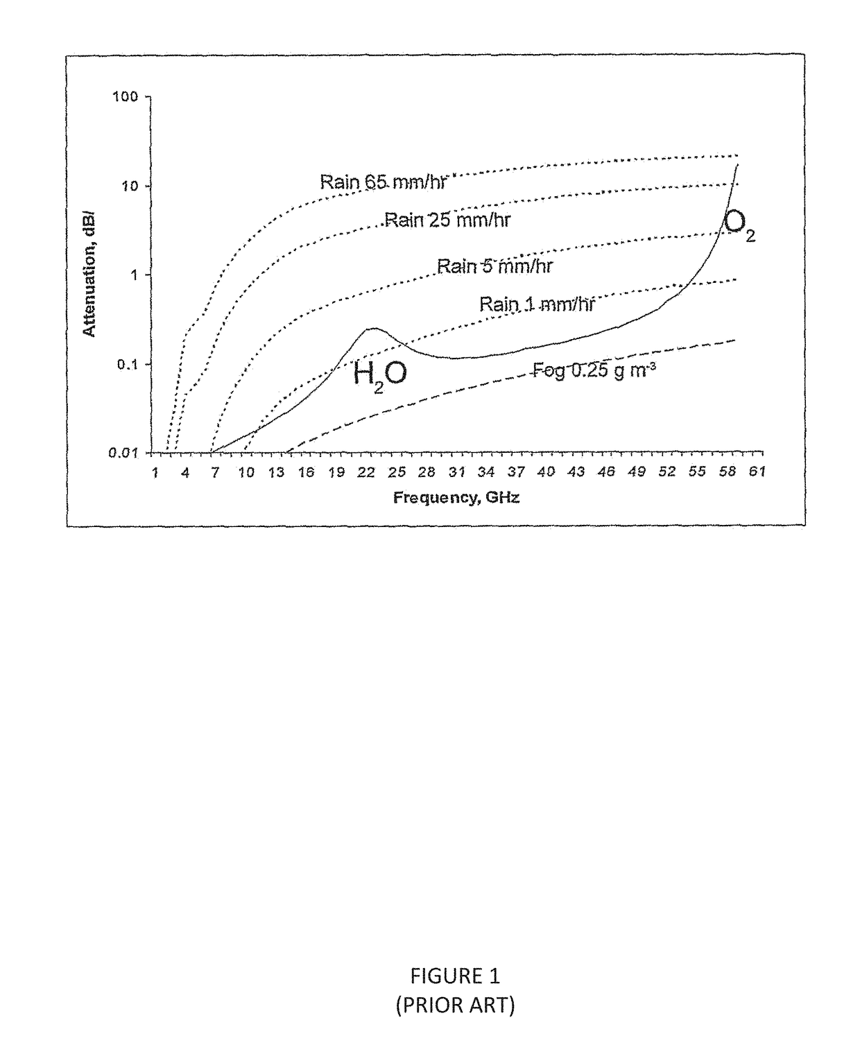
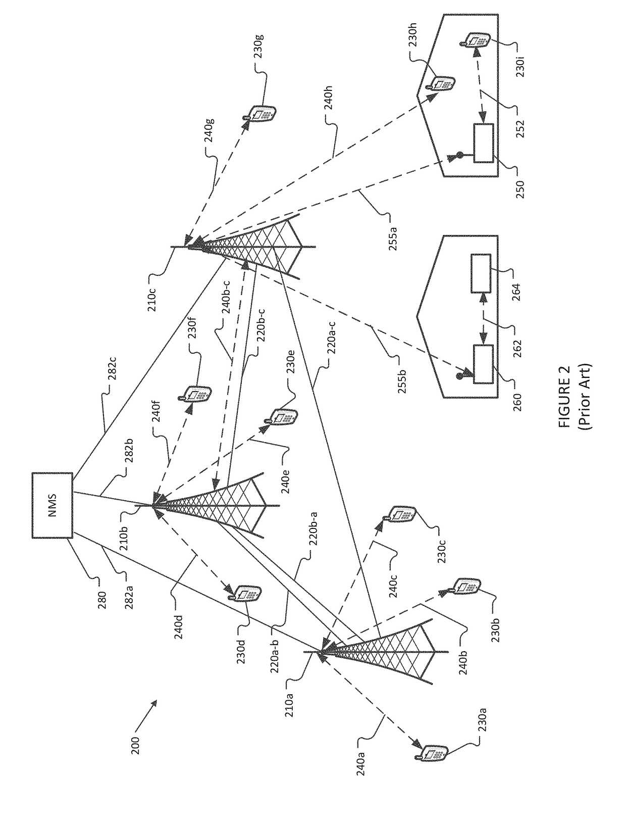
Attenuation of cellular microwave links (240a-240h) due to precipitation can be relatively small (e.g. less than 10 dB) such that perturbations in attenuation due to precipitation or other atmospheric conditions of interest can be difficult to differentiate from random or non-rain related variations based on individual link signal measurements.
The constantly changing link topologies of cellular networks make the existing static topology algorithms for characterizing and mapping precipitation unworkable, particularly when real-time prediction of the precipitation is needed.
Real time data collection and prediction requires much shorter measurement intervals and results in data volumes increasing many-fold.
When many of these microwave links are dynamically changing with respect to location and even presence, and furthermore when they may vary in frequency usage from minute to minute, the ability to statically map links to area coverage becomes much harder.
Taken together, these challenges mean that existing systems fail from an information handling perspective in their ability to provide real-time prediction of precipitation amounts.
The prior art approaches collectively demonstrate notable deficiencies when applied to current and planned microwave-based network topologies.
First, they are hindcast model development techniques, which provide, by definition, a forecast after the event has happened.
They are also limited with respect to the data sources used, as these data sources have built in inaccuracies due to limits in the underlying models, and are based upon unchanging configurations of networks and data sources.
Accordingly, they are non-generalizable and are insufficient to support real-time analysis and prediction of weather-related phenomena.

Method used


Image

  • Real-Time Precipitation Forecasting System
  • Real-Time Precipitation Forecasting System
  • Real-Time Precipitation Forecasting System

Examples


Embodiment Construction

6.1 Overview

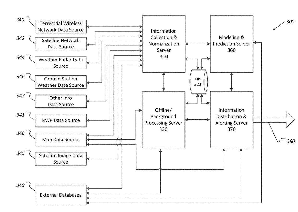
[0080]The systems and methods described herein provide a mechanism for collecting information from a diverse suite of sensors and systems, calculating the current precipitation and other atmospheric-based phenomena based upon these sensor readings, and predicting future precipitation and atmospheric-based phenomena. Unlike current systems, the described system and methods provide improved data collection and augmentation, dynamically updated data sets, significant accuracy improvements, and real-time projections.

[0081]“Real time” meteorology equipment, such as weather radar, provides precipitation maps showing precipitation intensities and locations on a short time interval, e.g., less than a fifteen minute interval, or optionally less than a five minute interval, or optionally a one minute interval or thereabout. Weather radar signals attenuate when passing through precipitation, so the precipitation maps derived from weather radar have known limitations as the signal i...


PUM


Abstract

A computerized method of processing data for use in weather modeling is provided. The method includes receiving, from a first data source, by a first server, microwave link data including signal attenuation information. The method also includes pre-processing, in real time, by the first server, the microwave link data, thereby producing pre-processed microwave link data, The method also includes storing the pre-processed microwave link data in a first data store. The method also includes receiving, from the first data store, by a second server, the pre-processed microwave link data. The method also includes processing, on a scheduled routine, by the second server, the pre-processed microwave link data using a data transform, thereby producing first weather data.

Description

1 CROSS REFERENCE TO RELATED U.S. PATENT APPLICATIONS[0001]The present application claims priority under 55 U.S.C. §119(e) to provisional U.S. Patent Application Ser. No. 62 / 354,320 (Docket No. CLI-001PR) filed Jun. 24, 2016, and provisional U.S. Patent Application Ser. No. 62 / 479,025 (Docket No. CLI-002PR) filed Mar. 30, 2017, both of which are incorporated herein by reference in their entirety and for all purposes.2 COPYRIGHT NOTICE[0002]A portion of the disclosure of this patent document may contain material that is subject to copyright protection. The copyright owner has no objection to the facsimile reproduction by anyone of the patent document or the patent disclosure, as it appears in the Patent and Trademark Office patent files or records, but otherwise reserves all copyright rights whatsoever. The following notice shall apply to this document: Copyright © 2017, ClimaCell, Inc.3 BACKGROUND3.1 Field of the Invention[0003]The exemplary, illustrative, technology herein relates ...

Claims


Application Information

Patent Timeline
IPC IPC(8): G01W1/10G01S13/95
CPCG01W1/10G01W2203/00G01S13/95G01W1/14Y02A90/10
Inventor ELKABETZ, SHIMONZLOTNIK, ITAIGOFFER, REIRIBNIK, JACOBNOSSENSON, NIRBAR-OR, ROTEMGINTER, KARL
Owner REMOTE SENSING SOLUTIONS INC
Learn More