Using a cbct bone scan to design a dental abutment

Active Publication Date: 2018-01-04
3SHAPE AS
View PDF7 Cites 3 Cited by
  • Summary
  • Abstract
  • Description
  • Claims
  • Application Information

AI Technical Summary

Benefits of technology

The patent text is about a method for designing a digital abutment that matches the surrounding dentition. This is done by using data about the patient's teeth or any type of restoration. By conforming to the anatomy and existing tissue volume, the abutment and restoration create a seamless transition and an aesthetically pleasing final look. The technical effect is an improved design for abutments that results in a more natural and functional final look.

Problems solved by technology

However, this method of attaching the restoration invariably means that the screw access hole has to be lined up perfectly with the direction of the implant borehole.
In some situations, especially for anterior teeth, this arrangement will mean that the screw access hole would become an aesthetic liability.
However, it remains a problem to choose or design an abutment suited for each patient's specific situation.
It has not previously been possible to take the sub-gingival emergence profile of the adjacent teeth into account when creating the digital abutment design, because only a surface scan has been taken into consideration, or the abutment has been designed in a manual process using a physical model.

Method used


Image

  • Using a cbct bone scan to design a dental abutment
  • Using a cbct bone scan to design a dental abutment
  • Using a cbct bone scan to design a dental abutment

Examples


Embodiment Construction

[0043]In the following description, reference is made to the accompanying figures, which show by way of illustration how the invention may be practiced.

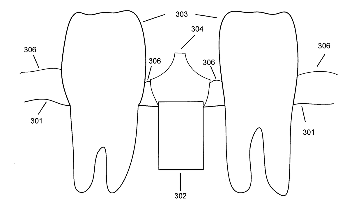
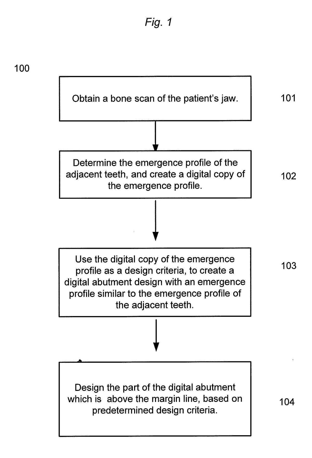
[0044]FIG. 1 shows an example of a method 100 according to an embodiment of the invention. In step 101, a bone scan of the patient's jaw is obtained. The scan may comprise a dental implant already fixed in the patient's jawbone. Obtaining the scan may involve the physical operation of a machine, and performing the scan on the patient. Obtaining may also mean loading a previously acquired scan into a computer. In step 102 the emergence profile(s) of the tooth or teeth adjacent to the site of the wanted abutment are determined, and a digital data representation of this emergence profile is generated. In step 103 the digital abutment design is created, using the digital data representation of the emergence profile of the adjacent teeth, so that the digital abutment design is designed with a substantially similar emergence profile. The e...


PUM


Abstract

Disclosed is a method of creating a digital abutment design of a customized dental abutment, the including comprising: obtaining a bone scan comprising a digital representation of at least a part of a patient's jaw including the surface of the jawbone; and designing the digital abutment design of the customized dental abutment; wherein the design of the digital abutment design is at least partly based on fulfilling a set of predefined design criteria including the relationship between the digital representation of the jawbone and the digital abutment design.

Description

FIELD OF THE INVENTION[0001]This invention generally relates to designing or selecting an implant abutment. More particularly, the invention relates to using a bone scan of a patient's jaw to design an abutment based on predetermined design criteria.[0002]Using the bone scan to constrain the design of the abutment while having a predetermined set of design criteria, will make it possible to design an abutment that will better fit a patient's specific situation.BACKGROUND OF THE INVENTION[0003]In the field of implant dentistry, it is known to use both cemented and screw retained restorations. A screw retained restoration has a screw access hole in the occlusal side, through which it is possible to fasten the restoration in the implant using a matching screw.[0004]However, this method of attaching the restoration invariably means that the screw access hole has to be lined up perfectly with the direction of the implant borehole. In some situations, especially for anterior teeth, this a...

Claims


Application Information

Patent Timeline
IPC IPC(8): A61C13/00A61B6/14A61B6/03A61B6/00G06F17/50A61C8/00
CPCA61C13/0004A61B6/032A61B6/14A61C8/005A61C8/008A61B6/4085G06F17/5009G06F30/20A61B6/51
Inventor FISKER, RUNE
Owner 3SHAPE AS
Why Eureka
Try Eureka