Machine generating centrifugal forces from eccentrics with variable radius

a centrifugal force and eccentric technology, applied in the field of centrifugal force, can solve the problems of not allowing the centrifugal force to generate a torque, affecting the operation of the machine, so as to achieve the effect of cancelling the gravitational weight of the body

Active Publication Date: 2018-01-04
JEBARI JAMEL
View PDF11 Cites 5 Cited by
  • Summary
  • Abstract
  • Description
  • Claims
  • Application Information

AI Technical Summary

Benefits of technology

[0104]An advantage of the present invention is that the generator (GCFEVR) and/or machine (MGCFEVR) uses the centrifugal forces (Fc) generated onto masses (M) to provide available output power, without the use of any drawback such as availability of the power source, weather condition or the like, since the centrifugal forces (Fc) are always available, wherever on the entire Universe.
[0105]Another advantage of the present invention is that the generator (GCFEVR) and/or machine (MGCFEVR) can produce either an output torque or an output thrust, depending on the mounting of the generator(s) onto the carrying structure.
[0106]A further advantage of the present invention is that the generator (GCFEVR) and/or machine (MGCFEVR), with rotating movement, can generate electrical energy by having the power torque feeding an electric generator, and/or can be an engine for all types of ground vehicles and others.
[0107]Yet another advantage of the present invention is that the generator (GCFEVR) and/or machine (MGCFEVR), with linear movement, can be easily applied...

Problems solved by technology

But the energy E(acc) has been used to provide a circular trajectory to the spacecraft, and is lost since this energy is not stored anywhere and under no form of energy!!!
Therefore, if we do find where this lost energy went, we will have a problem with the law of conservation of energy, since the energy cannot be neither lost or generated, it can only be transformed from one form to another.
It implies, effectively, the existence of a unknown form of “matter...

Method used


Image

  • Machine generating centrifugal forces from eccentrics with variable radius
  • Machine generating centrifugal forces from eccentrics with variable radius
  • Machine generating centrifugal forces from eccentrics with variable radius

Examples


embodiment 101

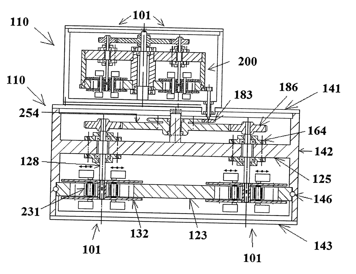
[0276]Further to the above, another embodiment of GCFEVR-1101 is shown in FIG. 23 as a further example, but with no limitations thereto. The embodiment 101, similarly than the embodiment of FIGS. 6 and 7 and also a sort of mix embodiment of the last two embodiments of FIG. 22, is shown with a simplified schematic plan view with a corresponding simplified schematic diagram of a typical curve of the total torque (Ct) of the centrifugal forces (Fc1+Fc2) generated by the two, diametrically opposite, masses (M1, M2) 120a, 120b about the main shaft (Axf) 202, for one 360-degree (2π-radian) rotation of the rotating shaft (Axt) 128 (angle ω), while being displaced along their eccentric closed trajectory (Traf) 150. More specifically, along the portions (a-b) and (c-d) of the bore (Tpi) 126 of the plate (Pci) 122, the radius of the trajectory of mass (M1) 120a decreases from (r) to (r−x) (along portion (a-b)) while the radius of the trajectory of the other mass (M2) 120b remains constant at ...

second embodiment

[0277]Similarly, other embodiments of GCFEVR-2s 102 are also shown in FIG. 24 as examples, but with no limitations thereto. The uppermost embodiment is essentially the embodiment of FIG. 11. The second embodiment is similar to the first one except that instead of having a diametrically oriented rectilinear portion it has a second typically semi-circular portion of the eccentric closed trajectory (Traf) 150, of smaller (or larger) radius, which requires that the masses (M) 120, always remaining in a same mass plane 172 (as seen in FIG. 11), are independently driven with respective sets of arms (br) 224 of two main parts (Mte1) 167, (Mte2) 168 of the mass driving member (Mte) 166 that rotate in opposite directions (ω1) and (ω2), respectively. Finally, the last and bottommost embodiment is similar to the second one except that instead of having the second typically semi-circular portion of the eccentric closed trajectory (Traf) 150 on a same mass plane 172, it is in a second mass plane...


PUM


Abstract

A generator (100) and/or machine (110) generating mechanical energy and functioning on the principle of exploitation of an energy allowing the existence of centrifugal forces (Fc) on masses (M) being displaced in rotation along an eccentric trajectory (150) within a system (130, 132, 166, 170, 190, 210) driving a progressive or sudden variation of their radius of rotation, principle of a generator of centrifugal forces from an eccentric with variable radius (100).

Description

FIELD OF THE INVENTION[0001]The present invention relates to the functioning principle of machines generating mechanical energy from energy being the basis or ground of the accelerated expansion of our Universe, and more specifically from centrifugal forces.BACKGROUND OF THE INVENTION[0002]Scientific Explanation[0003]In the following paragraphs, there will be provided simple examples that will be in contradiction with the well known first principle of thermodynamics (the Law of Conservation of Energy) . . . .[0004]It is well known in physics that any body in movement has a tendency to follow a rectilinear trajectory as long as it is not deviated by an external force. This is why whatever trajectories (other than rectilinear) can exist only with introduction of external forces at different times and different locations, or continuously in the case of elliptical or circular trajectories.[0005]In the following, we will focus on the trajectory of circular motion.[0006]During this type o...

Claims


Application Information

Patent Timeline
IPC IPC(8): F16H33/20F03G3/00
CPCF16H33/20F03G3/00F03G7/10F16C3/18H02K53/00F16C3/22F03G7/125
Inventor JEBARI, JAMEL
Owner JEBARI JAMEL
Why Eureka
Try Eureka